
Operating instructions

Wiring and assembly
5.3 Electrical configuration of the ET 200S
ET 200S
78 Operating Instructions, 08/2008, A5E00515771-06
5.3 Electrical configuration of the ET 200S
Galvanic isolation
In the ET 200S, isolation exists between:
● The load circuits/process and all other circuit components of the ET 200S
● The PROFIBUS DP interface in the interface module and all other circuit components
● The PROFINET interface in the IM151-3 PN interface module and all other circuit
components
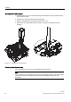
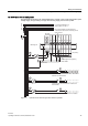
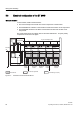
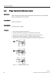
The figure below shows the voltage ratios for ET 200S with IM151-1. Only the primary
components are shown in the figure.
/
0
,0
0
0
3(
3(
/
0
,0
,0
/
0
(76EDFNSODQHEXV
(OHFWURQLFV
%DFNSODQHEXV
'3
,QWHU
IDFH
0RXQWLQJ
UDLO
(OHFWULFDO
LVRODWLRQ
%XV
LQWHUIDFH
(OHFWULFDO
LVRODWLRQ
3URFHVV
HOHFWURQLFV
(OHFWULFDO
LVRODWLRQ
(OHFWULFDO
LVRODWLRQ
(OHFWULFDO
LVRODWLRQ
(OHFWULFDO
LVRODWLRQ
3URFHVV
HOHFWURQLFV
3URFHVV
HOHFWURQLFV
7HUPLQDWLQJPRGXOH
(OHFWURQLF
PRGXOH
(OHFWURQLF
PRGXOH
(OHFWURQLF
PRGXOH
3RZHU
PRGXOH
3RZHU
PRGXOH
3RWHQWLDO,2
'3LQWHUIDFHSRWHQWLDO
3RWHQWLDOORJLFFLUFXLWU\
%XV
LQWHUIDFH
%XV
LQWHUIDFH
%XV
LQWHUIDFH
%XV
LQWHUIDFH
9'& 9'&
Figure 5-2 Potentials of the ET 200S with IM151-1