
User Manual


3
Building Technologies A6V10088169_f_--_--
Fire Safety 2016-04-20
9. Schliessen Sie die erweiterte Peripherie (Summer,
Taste 'Summer AUS' und Lampentest) gemäss
Anschlussschema an der Klemme X5 an.
10. Befestigen Sie die Synoptik-LEDs (5) auf dem
Grundrisstableau (Herstellung kundenseitig). Trennen
Sie falls notwendig die LED-Anschlüsse (4) pa
arweise
weiter auf.
11.
Schliessen Sie die Stecker (3) der Flachkabel (6) an
Stecker X11 bzw. X12 an.
12. Montieren Sie das Grundrisstableau in das
Synoptikgehäuse.
13. Bei Verwendung einer externen Speisung
montieren Sie diese am dafür vorgesehenen Ort (im
Gehäuse oder in unmittelbarer Nähe des Gehäuses).
14. Führen Sie anschliessend eine Funktionsprüfung
durch:
· Prüfen Sie die Ausgangsspannung (AC 12
V oder
DC 24 V).
· Testen Sie die Speisungsüberwachung, indem
Sie die Speisung unterbrechen und die Störungs-
meldungen auf dem Terminal kontrollieren.
15. Bringen Sie anschliessend das beigelegte
Anlagenschild gut sichtbar am Gehäuse an und
tragen Sie das Montagedatum ein.
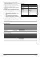
Technische Daten
Gewicht 232 g
Abmessungen (B x H x T) 106 x 200 x 45 mm
Lagertemperatur -20…+60 °C
Betriebstemperatur 0…+40 °C
Feuchte ≤95 % rel.
Gehäuse kundenseitig min. IP30
Einsatzhöhe max. 4000 m.ü.M.
Betriebsspannung ext. AC 11…22 V
DC 14…32 V
Betriebsstrom max. 45 mA
Ausgang Buzzer max. 5 mA / DC 12 V
en
Intended use
The mimic display driver FT2001-A1 for the FS20 fire
detection system is connected to the FDnet detector
line. It serves for system-wide event signaling. The
separately available flat cables have 48 LEDs in total,
which may be positioned in any housing, according to a
ground plan of the building.
Function
l 48 free programmable driver outputs
l Configuration of the driver outputs with the
Engineering tool
l Communication via FDnet, individually addressable
l Power supply via FDnet or via an external DC/AC
supply
l Connections for buzzer, button 'Local buzzer OFF',
lamp test and LED 'Operation
l 2 plug connections for flat cables with up to 24 free
positioned LEDs
Scope of delivery FT2001-A1
The scope of delivery comprises:
l P.c.b. with plug connections, mounted on base plate
l Type plate
Scope of delivery F50F410
The scope of delivery comprises:
l 2 flat cables, 50-poles, pre-assembled, with 24 LEDs
each
Safety notes
Danger of damage to persons and property
Please adhere to the following safety instructions:
l The devices are only intended for stationary mounting
in dry rooms.
l The devices may only be connected to the FDnet
detector lines.
l An external supply must be galvanically isolated from
the installation’s supply.