FC1008-E Fire control unit Technical specification Building Technologies Fire Safety & Security Products
Data and design subject to change without notice. / Supply subject to availability. © Siemens Switzerland Ltd 2004-2010 We reserve all rights in this document and in the subject thereof.
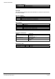
1 About this document ..............................................................................5 2 2.1 2.1.1 2.1.2 2.1.3 2.2 Safety regulations ...................................................................................7 Signal words and symbols ........................................................................7 Classification and meaning of signal words..............................................7 Symbols and their meaning ............................................................
8 8.1 8.2 8.3 8.3.1 8.3.2 8.3.3 8.3.4 8.3.5 8.3.6 8.3.7 8.3.8 8.3.9 8.3.10 8.3.11 8.3.12 8.3.13 8.3.14 8.3.15 8.3.16 8.3.17 8.3.18 8.3.19 8.3.20 8.3.21 8.3.22 8.3.23 8.4 8.5 Configuration.........................................................................................31 Programming user functions ...................................................................31 Programming steps .................................................................................32 Programmable functions ..........
About this document 1 About this document Purpose and scope This document describes the installation, function, commissioning, maintenance, troubleshooting and disposal of the product FC10xx. The consistent observance of the instructions ensures a trouble-free and safe application. Application area The information in this document applies from the hardware / software version 5.4.
About this document Reference documents Number/Version 007995 008099 Name Operating Manual FC10 Product data sheet FC1008/12 Download The most recently released technical documentation for customers can be found in the Siemens Intranet. Standard symbols Text in italic see (…) Result, note Quotation, exact match Cross reference Brackets contain supplementary text, suggestions etc.
Safety regulations 2 Safety regulations This chapter describes the danger levels and the relevant safety regulations applicable for the use of our products. Please read the work instructions as well as the chapter About this document thoroughly before beginning any work. 2.1 Signal words and symbols 2.1.1 Classification and meaning of signal words The danger level – that is, the severity and probability of danger – is indicated by the signal words listed below.
Safety regulations 2.2 Safety-relevant working instructions Country-specific standards The products are developed and produced in compliance with the relevant international and European safety standards.
System description 3 System description 3.1 General A conventional fire panel with unconventional features. The FC10 has all the functions that are necessary to build up small and medium size fire detection systems in a very efficient way. 3.
System description 3.3 Specified standards and options EN54-2 Basic functions Options and associated requirements 7.8 Output to fire alarm device EN54-1 / C 7.9.1 Output to fire alarm routing equipment EN54-1 / E 7.9.2 Alarm confirmation input from fire alarm routing equipment 7.10.
System description 3.
Installation 4 Installation 4.1 Assembly 3 2 4 4 6 5 9 11 7 8 10 Pos 1 2 3 4 5 6 7 8 9 10 11 Components Mains connection and circuit breaker (fuse), factory mounted.
Installation 4.2 Mounting 4 1 2 3 6 5 Procedure 1. Remove front cover 2. Determine mounting location (not behind a door) 3. Mark position of mounting screws (use enclosed drilling template) and drill holes. Installation accessories not included in cabinet: – screws min. 4x50mm – plastic dowels – c-shaped washers or lock washers 4. Mount chassis, if required with distance sleeves (1) 5. Break out cable entries (3) and mount cable glands (PG11) if required (2) 6.
Function and design 5 Function and design 5.1 Mainboard hardware settings CN1/2 ON ON PU10 CN7/8 CN3/4 PU18 PU9 PU11 1 3 CN5/6 CN14 ON ON F4 CN26 PU26 PU16 PU19 PU8 PU7 PU6 PU5 PU4 PU20 1 8 PU3 PU2 PU1 PU15 PU14 F2 F1 PU13 PU12 1 3 CN9 CN10 CL23 CL24 CN11 PU25 PU17 Ref PU1...
Function and design 5.2 Peripheral connections 5.2.1 Mainboard Z-diode 5,6V 1N4007 _ _ + F1 _ + FAULT RT ALARM RT FAULT RT DRIVER LIN1 LIN2 LIN3 LIN4 LIN5 LIN6 LIN7 LIN8 ALARM 1 2 ALARM 1/2 + _ + _ + _ + _LIN1 _ LIN2 _ LIN3 _ LIN4 + + + + _ + _ + _ + _ + LIN5 _ _LIN6 _LIN7 _LIN8 + + + + F2 _ + OUT 24V CL22 F4 NOTE Do not connect driver outputs directly to plus potential! Outputs may be damaged. In case of fire the maximum current is, see I max.
Function and design Driver outputs Mode manned Alarm 1 Alarm 2 Disable Fault Alarm 1/2 Zone 1 - 8 5.2.
Function and design 5.2.3 Control line extension card Summery The optional control line extension card features 4 monitored control outputs (control line 3 - 6). The following devices can be connected to the control outputs: – Alarm devices like horns or flashlights – Remote fire control installations – RT devices Functionality The control outputs of control lines 3 – 6 have basically the same features as the control outputs of control lines 1 and 2.
Function and design 5.2.4 Evacuation Summary The EVAC module features 4 monitored control outputs for alarm devices. The outputs can be activated either manually or automatically via fire detection control unit. When automatically activated, one or more control outputs can be allocated to each detector zone. The allocation is made in programming step 31. The control outputs are manually activated via operating panel. Note: Ref CN4 F1 F2 F3 F4 The control lines have to be closed with EOL FCE1002.
Function and design Connection to fault information according EN54-2 output J EN54-1 FAULT RT ALARM RT 5.2.5 680 Ω 10 kΩ (+ +) 1) 100 mA/T FAULT RT 2) 1) 2) (+ +) 12 V (– –) Extra relays 12 VDC, order to be done locally assembly place see page 12 pos. 9 Extra fuse in a safety housing, order to be done locally 100 mA/T 19 Building Technologies Fire Safety & Security Products A6V10265083_b_en_NL 04.
Function and design 5.3 5.3.1 Event processing Alarm The processing of alarm events is programmable mainly to prevent the unnecessary turnout of fire department for minor incidents. It involves personnel in the alarming sequence and relies on the operating mode manned. The system has to be run in operating mode manned as long as the responsible personnel is present. Mode manned has to be de-activated if the responsible personnel leaves the building.
Operation and indicator elements, mode of operation (PMI) 6 Operation and indicator elements, mode of operation (PMI) 6.1 Operating panel 6.1.1 General The system operating panel is also called Person Machine Interface - PMI.
Operation and indicator elements, mode of operation (PMI) 6.1.
Operation and indicator elements, mode of operation (PMI) 6.1.3 Operating keys Keys 1 12 2 8 3 Keys 4 5 6 7 1 2 3 4 Nr 1 2 Labelling Silence buzzer Acknowledge 10 11 Access Level 2 Level 2 3 4…7 Reset 1/2/3/4 Level 2 -- 8 Manned/ Unmanned Level 2 and and Cancel delay Level 1 Lamp test Sounder test Level 1 9 9 9999 Function to de-activate the buzzer to acknowledge Alarms and Faults to stop horn test before running time (30 sec.
Operation and indicator elements, mode of operation (PMI) 6.1.
Operation and indicator elements, mode of operation (PMI) 6.2 EVAC module Operating panel The EVAC module has a separate operating panel integrated in the unit. The panel basically consists of LED and keys. EVACUATION LED 6 All call LED 3 System ON LED 4 Disabled LED 5 Fault LED 1 ONTRUIMING LED 3 Key 2 Key 3 Start Zone 1 Key 1 ground floor west LED 4 Uitgeschakeld Storing LED 1 Zone 1 1 VERD.
Operation and indicator elements, mode of operation (PMI) 6.3 Display module 6.3.
Operation and indicator elements, mode of operation (PMI) 6.3.3 Set clock Set date and time 1. Give operating access on level 2 – the system may not display any alarm or fault 2. Hold key reset, key in 4233, release key reset and confirm by pressing key acknowledge – LED manned and operating access flash alternately and display shows "1_.XX" 3. Set year with the numeric keys 1 (up) or 2 (down) – confirm setting with zone key 1 then press key reset to proceed to next option (month, day, etc.
Operation and indicator elements, mode of operation (PMI) 6.3.4 Poll service informations The following information can be displayed on the display module: last change of configuration (date/time and check sum) last test alarm (date/time and zone number) version of firmware Requirement Queries about service information are only possible if there is no alarm and operating access on level 2 is given. Procedure 1.
Commissioning 7 Commissioning 7.
Commissioning 7.2 Testing peripheral devices Procedure Testing smoke detectors with DZ1193 or RE6 1. Set zone to mode detector test 2. Place testing unit on detector head 3. Wait until LED at detector head is on 4. Remove testing unit - automatic Reset of test alarm after 10s 5. Set zone to mode normal operation Testing heat detectors RE6T 1. Set zone to mode detector test 2. Place testing unit on detector head and turn on heater 3. Wait until LED at detector head is on 4.
Configuration 8 Configuration 8.1 Programming user functions In order to fulfill the local requirements, the programmable user functions may be adjusted by the single programming steps. 1 2 3 4 5 6 1 2 3 1 2 9 10 1 3 4 11 12 2 5 13 6 14 7 15 8 16 4 7 3 4 9999 4 Procedure to enter programming mode 1. Set system to state non-alarm and provide operating access level 2 2.
Configuration 8.2 Programming steps 1 1 2 2 3 3 4 5 6 1 2 9 10 1 3 4 11 12 2 5 13 6 14 7 15 8 16 4 3 4 9999 7 4 The selected programming steps are indicated at display module (4). The setting of an option can be selected with the zone keys (6) and is indicated with the corresponding red and yellow zone LED (5).
Configuration Display module programming steps Step 22 23 24 25 26 Define function indicating mode display Function display mode Function alarm counter switching mode manned/unmanned display switching time switching time summer/winter time switching time manned/unmanned Time 1 Time 2 EVAC programming steps Step 31 32 Define function Connect detector zones 1 – 8 to EVAC control lines 1 – 4 Change alarm stage to activate EVAC control lines 1 – 4 33 Building Technologies Fire Safety & Security Prod
Configuration 8.3 Programmable functions 1 1 2 2 3 3 4 5 6 1 2 9 10 1 3 4 11 12 2 5 13 6 14 7 15 8 16 3 4 9999 4 7 4 Procedure 1. Select the desired step with key (2) or (3) 2. Press the zone keys (6) as many times until the desired option is indicated with the corresponding zone LED (5) according to the following tables. 8.3.1 Step 1, timer V1 Option Setting Key Function: Timer V1 on alarm or fault in mode manned 1 0.5min zone 1 2 1min 3 2min 4 3min zone 2 5 4min 8.3.
Configuration 8.3.3 Step 3, zone processing on alarm Option Setting Function: Zone alarm processing (zone type) 1 via timer V1/V2 2 direct (timer bypassed) 1) 3 Alarm 0 (internal) 1) - RT and timer V1/V2 not initiated - Horn activated (unless disengaged in step 7) 4 via timer V1/V2, but call points always initiate Alarm 2 (direct) 2) 8.3.4 Key LED zone 1 - x Red yellow Zone 1 - x Default off on on on 1) If all zones are set to direct or internal, the function manned/unmanned is disabled.
Configuration 8.3.6 Step 6, measures against false alarms Option Setting Function: Zone with alarm verification 1 no alarm verification 2 Alarm only if second Alarm within 60sec 1st alarm = automatic Reset with short flash up of zone LED Function: Zone disabled in mode manned 3 not disabled 4 disabled as long as mode manned is active Key LED zone 1 - x Red yellow zone 1 - x Default off on zone 1 - x Default off on Note: – These measures are only justified on severe environmental conditions.
Configuration 8.3.11 Step 11, cross zoning Option Setting Key LED zone 1 - x Red yellow Function: Zone pair in cross-zoning on alarm zone A+B Default off 1 no cross-zoning on 2 cross-zoning type 1 zone A or B = no Alarm * zone A + B = Alarm 1 3 cross-zoning type 2 on zone A or B = Alarm 1 zone A + B = Alarm 2 4 Don’t use this option on on Remark: Only possible with defined zone pairs 1+2, 3+4 up to 11+12. Named in table with A and B. Procedure: 1.
Configuration 8.3.14 Step 14, delay mains failure 8.3.
Configuration 8.3.17 Step 22, indicating mode display Option Setting Key Function display mode 1 clock, alarm counter and event memory 2 alarm counter only (clock turned off) 3 clock and event memory 4 clock and alarm counter Function alarm counter 5 RT-alarms only 6 zone alarms only 7 RT-alarms and zone alarms alternating 8.3.
Configuration 8.3.22 Step 31, allocate detector zones to EVAC control lines Option 1 2 3 4 5 Setting No allocation In case of alarm 1, activate EVAC control line 1 In case of alarm 1, activate EVAC control line 2 In case of alarm 1, activate EVAC control line 3 In case of alarm 1, activate EVAC control line 4 Key LED Zones 1–8 red Zone 1-8 numeric 1 numeric 2 1 2 yellow yellow Default off on 3 yellow 4 yellow on on numeric 3 on on numeric 4 Procedure 1. Select programming step 31 2.
Configuration 8.
Configuration Display module programming steps Step 22 23 24 25 26 Function indicating mode display Function display mode Function alarm counter Automatic switching mode manned/unmanned display switching time switching time summer/winter time switching time manned/unmanned Time 1 Time 2 Factory setting (Default) Individual Setting clock, alarm counter and event memory Rt-Alarms only no …………………………………….. …………………………………….. …………………………………….. yes yes …………………………………….. ……………………………………..
Maintenance 9 Maintenance 9.1 General The fire detection installation requires only little maintenance work.
Maintenance Operating panel Performance checks Clean front panel with mild soap - do not use aggressive or abrasive solvents Activate lamp test Check correctness and readability of the inscription stripes Check key-click of each key Check access facility Interval in years 1 2 5 X X X X X Inside control unit Performance checks Check earth connections Visual check of battery Remove dust Interval in years 1 2 5 X X X 44 Building Technologies Fire Safety & Security Products A6V10265083_b_en_NL 04.
Trouble shooting 10 Trouble shooting 10.1 Interpretation of fault LED flashing LED LED LED 1 2 7 8 16 3 4 9 10 5 11 12 13 6 14 1 LED 9 LED flashing Fault 10 Earth fault 11 Power fault Flashing fast Flashing slow 12 System fault 13 Alarm horn fault 14 Fire controls fault 15 RT-Fault 23 RT-Alarm Yellow LED zone x Fault zone Display Indicates 88.
Components and spare parts 11 Components and spare parts 11.1 Components Type FC1008-E 11.2 11.3 Part number S54380-C4-A40 Description control unit 8 zones Remarks Type FCA1003 Z3B171 Part number S54380-66-A1 4843830001 Remarks FCA1007 FA2004-A1 FA2005-A1 A6E60500026 A5Q00019354 A5Q00019677 Description control card fire control relay 1 contact 250 VDC/10 A kit key switch FA2004-A1 battery 12V, 12 Ah, VDS FA2005-A1 battery 12V, 17 Ah, VDS Accessories incl.
Disposal and environmental protection 12 Disposal and environmental protection 12.1 General The customer is in charge of the disposal of Siemens fire detection systems. In case of any uncertainty relative to the disposal process, which might cause danger to people or to the environment, please consult the Technical Customer Service of Siemens Building Technologies AG. The putting out of service and disposal of a system must be communicated to Siemens Building Technologies AG. 12.
Siemens Switzerland Ltd Industry Sector Building Technologies Division International Headquarters Gubelstrasse 22 6301 Zug, Switzerland Tel. +41 41 - 724 24 24 © Siemens Switzerland Ltd 2004-2010 Data and design subject to change without notice. www.siemens.com/buildingtechnologies Document no. A6V10265083_b_en_NL Manual - Edition 04.