FC10 Fire detection control unit Operating instructions Fire & Security Products Siemens Building Technologies
Liefermöglichkeiten und technische Änderungen vorbehalten. Data and design subject to change without notice. / Supply subject to availability. Sous réserve de modifications techniques et de la disponibilité. © 2004 Copyright by Siemens Building Technologies AG Wir behalten uns alle Rechte an diesem Dokument und an dem in ihm dargestellten Gegenstand vor.
1 About this document ..............................................................................5 2 2.1 2.1.1 2.1.2 2.1.3 2.2 Safety regulations ...................................................................................6 Signal words and symbols ........................................................................6 Classification and meaning of signal words..............................................6 Symbols and their meaning ............................................................
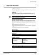
About this document 1 About this document Purpose of the document This document describes the operation of the fire detection control unit. Please read the operating instructions thoroughly, to ensure that you manage the operation of the control unit in case of fire. Target group This document is intended for persons operating the fire detection control unit.
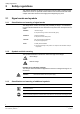
Safety regulations 2 Safety regulations This chapter describes the danger levels and the relevant safety regulations applicable for the use of our products. Please read the work instructions as well as the chapter "About this document" thoroughly before beginning any work. 2.1 Signal words and symbols 2.1.1 Classification and meaning of signal words The danger level – that is, the severity and probability of danger – is indicated by the signal words listed below.
Safety regulations 2.2 Safety-relevant working instructions Country-specific standards The products are developed and produced in compliance with the relevant international and European safety standards.
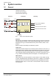
System overview 3 System overview 3.1 General The fire detection system consists of the following modules: Detectors (detection) Control unit (evaluation) Alarm devices (alarming) Detection Evaluation Detector zone Manual call point zone Line 1 Line 2 Fire control installations 1 Mixed zone Alarming 2 3 8888 4 Line 3 Alarm devices Remote transmission Alarm Remote transmission Fault Detector zone Line x Supply 115/230VAC Fig.
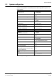
System overview 3.2 System configuration Each fire detection system is configured individually. The configuration has an influence on the operation. The table below shows the configuration of your fire detection system.
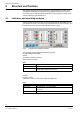
Structure and function 4 Structure and function This chapter describes the setup and function of the fire detection control unit. It provides the reader with an overview of the possibilities offered by the fire detection control unit. An exact description of the different procedures is included in the sections 'Operation' and 'Maintenance'. 4.1 Indicators and operating modules 1 2 3 Zone keys 9999 4 Numerical keys Fig.
Structure and function Indicator module The indicator module is optional and is possibly not equipped yet. The operation thus differs largely and is mentioned in this manual in the corresponding sections. Key switch The key switch is optional and is possibly not equipped yet. It serves for enabling operation and has the same function as the password (see section 'Enabling operating level 2'). 4.2 Function 4.2.
Structure and function 4.2.3 Operating modes The fire detection control unit has the following mode of operations: 'Unmanned' This operating mode must be set when no instructed staff is present. In case of alarm or fault, remote transmission (e.g. to the fire brigade) is activated immediately. 'Manned' In this operating mode instructed staff is present, who is involved in the process in case of alarm or fault. In this operating mode, an alarm or fault signal activates the remote transmission (e.g.
Structure and function 4.2.4 Alarms An alarm is triggered when: a manual call point has been activated, an automatic detector has detected a fire.
Structure and function 4.2.5 Faults The fire detection control unit includes a comprehensive self-monitoring functionality. When the control unit detects an error in the system (e.g. a detector is removed), this is signaled as fault. Faults are normally transmitted to a receiving station. Faults should always be remedied as quickly as possible. The process with a fault depends on the set operating mode 'Manned' or 'Unmanned' (see figure below).
Structure and function 4.2.6 Indicator module (on option) The indicator module is optional and possibly not equipped in your system. The indicator module can display the following information: Number of registered alarms (alarm counter) Expiry of the delay periods V1 and V2 in case of alarm Time Events with date and time, e.g. fault (recallable event memory) 4.2.7 Maintenance possibilities Fire detection systems must be serviced regularly.
Operation 5 Operation 5.1 Normal operation In normal operation, the following LED light up: 'System ON' 'Mode Manned' (if the control unit is in operating mode 'Manned' ist) 5.2 Operating level 2 enabled General Normally the fire detection control unit is blocked for operation. Operation (operating level 2) is enabled either by entering the password or by means of the key. Password To enable operating level 2 with the password, proceed as follows: 1. Enter the password using the numeric keys.
Operation 5.3 Set operating mode 'Manned'/'Unmanned' General You can recognize the set operating mode on the LED 'Manned'. LED 'Manned' On Off Operating mode 'Manned' 'Unmanned' When instructed persons are in the building, the operating mode 'Manned' should be set. For this reason the first instructed person entering the building should set the fire detection control unit to operating mode 'Manned'.
Operation 5.4 Operation in case of alarm with alarm organization ('Manned') Important Alarms always require the quick and controlled intervention of the persons present. For this reason, read this section thoroughly to make sure you make the right decisions in case of emergency.
Operation Copy this page and keep it ready in case of alarm! Alarm (red LEDs are flashing rapidly) Press red key Read off fire location Go to the fire location Decide! No fire Fire Back to the control unit Activate next manual call point F Press green key 19 Siemens Building Technologies Fire & Security Products 007995_a_en_--.doc 04.
Operation 5.5 Activating an evacuation Overview It is possible to activate an evacuation without an alarm being triggered by a detector. In this case no alarm message is transmitted to the fire brigade. Procedure To activate an evacuation, please proceed as follows: 1. Enable the operating level 2 (password or key). 2. Press the key 'Evacuation'. The LED 'Evacuation' lights up. The fire alarm devices (e.g. horns) are activated 3. To cancel the evacuation, press the key 'Evacuation' again.
Operation 5.6 Switching off system parts In certain situations (e.g. renovation work) it may make sense to switch off parts of a system. When a system part is switched off, the LED 'Part of system OFF' is always on. WARNING! 5.6.
Operation 5.6.2 Temporarily switching off alarm devices Overview To avoid the unintended activation of alarm devices, the alarm devices must be switched off in exceptional cases. WARNING! Alarm devices that have been switched off are not activated in case of alarm! For this reason, always switch these alarm devices on again as soon as normal operating conditions are prevailing again! Procedure To switch the alarm devices off, proceed as follows: 1. Enable the operating level 2 (password or key). 2.
Operation 5.6.4 Switching fire control installations and alarm devices temporarily off Overview To avoid the unintended activation of fire control installations and alarm devices, these must be switched off in exceptional cases.
Operation 5.6.6 Temporarily blocking remote transmission of alarms Overview If in exceptional cases alarms shall not be remotely transmitted, the remote transmission of alarms must be blocked.
Operation 5.7 Polling event memory Overview This function is only available with control units with an indicator module. The event memory records event with date and time. These event can be polled at any time. Each event has an event number. This number is displayed on the indicator module (e.g. E.012.). The most recent event has the lowest number (E.001.). The event is indicated by means of the LED. An alarm on zone 4, for example, is indicated by the red zone LED 4.
Operation 5.8 Setting date and time Overview This function is only available with control units with an indicator module. Control units with an indicator module are equipped with an integrated clock. In countries in which the Central European Summertime is valid, this clock automatically switches between summer and winter time. In all other countries the settings must be made manually.
Maintenance 6 Maintenance 6.1 Important notes Only a well-serviced fire detection system remains functional in case of emergency. For this reason, regularly perform the recommended maintenance work or have them performed by a service technician (see table below). At any rate, observe the local regulations. Maintenance work Check detector network Check control unit Simulate alarm Simulate fault Tab. 5 Maintenance work intervals 6.
Maintenance 6.3 Check control unit Overview This test intends to check whether the optical and acoustic elements of the control unit function faultlessly. Procedure Check the control unit as follows: 1. Press the key 'Lamp test/Sounder test' The buzzer sounds. All LEDs light up. 2. Check whether all LEDs light up and the buzzer sounds. 6.4 Simulate alarm Overview By simulating an alarm you can check the following functions of the fire detection system: Remote transmission (e.g.
Maintenance 6.5 Simulate fault Overview By simulating a fault it is possible to check the remote transmission equipment for faults (e.g. transmission to the fire brigade). WARNING! Before simulating a fault, inform accordingly to avoid an unnecessary turning out. Procedure Simulate a fault as follows: 1. Inform accordingly on the pending simulation. 2. Press the numerical key '2' and keep it pressed. 3. Press the zone key '1'. A fault is simulated. The yellow zone LED is flashing rapidly.
Troubleshooting 7 Troubleshooting This section provides you with information in case of a system disturbance, or when the system is not in normal operation. The table below provides a list of possible faults with notes on possible causes. Fault LED 'Fault' is flashing Cause/Remedy Fault in the system 1. Check whether another yellow LED is flashing. 2. If no other yellow LED is flashing, contact the service technician. LED 'Fault power supply' Fault in the power supply is flashing 1.
Siemens Building Technologies AG Alte Landstr. 411 CH-8708 Männedorf Tel. +41 1 - 922 6111 Fax +41 1 - 922 6450 www.sbt.siemens.com Document no. 007995_a_en_-- Edition 04.