
Technical Manual
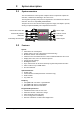
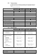
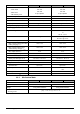

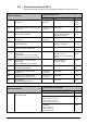
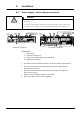
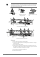
Table Of Contents
- 1 About this document
- /
- The information provided in this manual is a summary of the key procedures and functions required to assemble, install, operate, commission and repair the system.
- It is intended to provide experienced and qualified personnel a guide on the required processes.
- The technical manual applies to the Cerberus FIT fire control panel FC12x series.
- The information in this document is intended for the following target groups:
- The reference document has the following designation:
- ID_x_en_--
- x = version, en = English, -- = international
- The list below is used as a reference for the fire control panel FC12x and as a supplement to this document.
- Version
- Edition date
- Brief description
- 2 Safety regulations
- 3 System description
- /
- 4 Installation
- 5 Function overview
- 6 Operation
- AVC
- DIRECT
- Manned
- Unmanned
- The actual events will display all pending events.
- The panel is protected against unauthorized user operation.
- Therefore enter the password or turn the key switch (optional).
- The panel is protected against unauthorized user operation. Therefore enter the password or turn the key switch (optional).
- The alarm counter counts all fire alarms.
- All events such as alarm(s), fault(s), isolation(s), input(s) and output(s) activation are stored in a history log.
- Manual logout to access level 1.
- Each zone can be isolated individually.
- Enable the test mode for each zone.
- Disable outputs generally and / or individually.
- Information about the software is displayed.
- Exit with
. - Exit with
. - Exit with
. - 7 Programming
- Input customer text for:
- 8 Tool function
- 1. Start the Hyper Terminal and enter an appropriate name.
- 2. Select communication port.
- /
- Make sure your PC is connected to the FDUZ22x box and the driver is installed.
- /Make sure your PC is connected to the FDUZ22x box and the driver is installed.Check the communication port on the device manager.
- /
- /
- 1. Select the following option on the panel.
- 2. Enable the Hyper Terminal to receive data.
- /
- /
- /
- /
- /
- 1. Select the following option on the panel.
- 2. Enable the hyper terminal to receive data.
- /
- /
- /
- /
- /
- 1. Select the following option on the panel..
- 2. Enable the hyper terminal to 'Send file'.
- /
- /
- /
- 1. Click
. - 2. Select the folder 'Settings' and click 'ASCII Setup'.
- 5. PC will display as below. Press '2'.
- 6. 'CC…' shows the connection is established and ready for transfer.
- /
- /
- /
- 9 Commissioning
- 10 Maintenance
- 11 Battery capacity
- 12 Trouble shooting
- 13 Components and spare parts
- 14 Disposal and environmental protection
- Appendix A: Site configuration, Factory Setting
- Appendix B: Switch mains to AC 115 V
- Appendix C: History log

A6V10393190_j_en_-- 11
Safety–relevant instructions
National standards, regulations and legislation
Siemens products are developed and produced in compliance with the relevant
European and international safety standards. Should additional national or local safety
standards or legislation concerning the planning, assembly, installation, operation or
disposal of the product apply at the place of operation, then these must also be taken
into account together with the safety regulations in the product documentation.
Electrical installations
WARNING
Electrical voltage
Electric shock
Work on electrical installations may only be carried out by qualified electricians or by
instructed persons working under the guidance and supervision of a qualified
electrician, in accordance with the electro technical regulations.
Wherever possible disconnect products from the power supply when carrying out
commissioning, maintenance or repair work.
Lock volt-free areas to prevent them from being switched back on again by mistake.
Label the connection terminals with external voltage using a 'DANGER External
voltage' sign.
Route mains connections to products separately and fuse them with their own,
clearly marked fuse.
Fit an easily accessible disconnecting device in accordance with IEC 60950-1
outside the installation.
Produce earthing as stated in local safety regulations.
Assembly, installation, commissioning and maintenance
The panel is designed for operation in a closed room, please note the
environmental conditions in this technical manual.
Please check the country specific regulations and guidelines during installation and
programming of the fire control panel.
Only operate the fire control panel with housing closed due to the danger of an
electric shock.
If you require tools such as a ladder, these must be safe and must be intended for
the work in hand.
When starting the fire control panel ensure that unstable conditions cannot arise.
Ensure that all points listed in the 'Testing the product operability' section below are
observed.
You may only set controls to normal function when the product operability has been
completely tested and the system has been handed over to the customer.