
Technical Manual
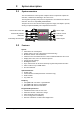
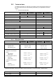
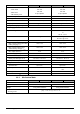

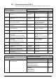
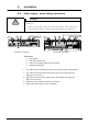
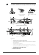
Table Of Contents
- 1 About this document
- /
- The information provided in this manual is a summary of the key procedures and functions required to assemble, install, operate, commission and repair the system.
- It is intended to provide experienced and qualified personnel a guide on the required processes.
- The technical manual applies to the Cerberus FIT fire control panel FC12x series.
- The information in this document is intended for the following target groups:
- The reference document has the following designation:
- ID_x_en_--
- x = version, en = English, -- = international
- The list below is used as a reference for the fire control panel FC12x and as a supplement to this document.
- Version
- Edition date
- Brief description
- 2 Safety regulations
- 3 System description
- /
- 4 Installation
- 5 Function overview
- 6 Operation
- AVC
- DIRECT
- Manned
- Unmanned
- The actual events will display all pending events.
- The panel is protected against unauthorized user operation.
- Therefore enter the password or turn the key switch (optional).
- The panel is protected against unauthorized user operation. Therefore enter the password or turn the key switch (optional).
- The alarm counter counts all fire alarms.
- All events such as alarm(s), fault(s), isolation(s), input(s) and output(s) activation are stored in a history log.
- Manual logout to access level 1.
- Each zone can be isolated individually.
- Enable the test mode for each zone.
- Disable outputs generally and / or individually.
- Information about the software is displayed.
- Exit with
. - Exit with
. - Exit with
. - 7 Programming
- Input customer text for:
- 8 Tool function
- 1. Start the Hyper Terminal and enter an appropriate name.
- 2. Select communication port.
- /
- Make sure your PC is connected to the FDUZ22x box and the driver is installed.
- /Make sure your PC is connected to the FDUZ22x box and the driver is installed.Check the communication port on the device manager.
- /
- /
- 1. Select the following option on the panel.
- 2. Enable the Hyper Terminal to receive data.
- /
- /
- /
- /
- /
- 1. Select the following option on the panel.
- 2. Enable the hyper terminal to receive data.
- /
- /
- /
- /
- /
- 1. Select the following option on the panel..
- 2. Enable the hyper terminal to 'Send file'.
- /
- /
- /
- 1. Click
. - 2. Select the folder 'Settings' and click 'ASCII Setup'.
- 5. PC will display as below. Press '2'.
- 6. 'CC…' shows the connection is established and ready for transfer.
- /
- /
- /
- 9 Commissioning
- 10 Maintenance
- 11 Battery capacity
- 12 Trouble shooting
- 13 Components and spare parts
- 14 Disposal and environmental protection
- Appendix A: Site configuration, Factory Setting
- Appendix B: Switch mains to AC 115 V
- Appendix C: History log

A6V10393190_j_en_-- 17
3.4 Standard and options EN 54
The fire control panel is designed to comply with the requirements of EN 54 part 2 / 4.
EN 54-2 Definitions
The EN 54-2 options are fulfilled if the following
configurations are used.
Installation Configuration / Operation Chapter
7.8
Output to fire alarm device
EN 54-1 / C
Monitored output
e.g. OUT 1
Sounder control
7.1.2
6.4.2
7.2.6
7.9.1
Output to fire alarm routing equipment
EN 54-1 / E
Monitored output
e.g. OUT 2
Alarm dialer 7.1.2
7.2.4
7.9.2
Alarm confirmation input from fire
alarm routing equipment
Input
Dialer device confirmation
signal; LED fire brigade
activated via input
7.1.3
7.2.4
7.10.1
Outputs to fire protection equipment
EN 54-1 / G
Monitored output
e.g. OUT 4
Fire output 7.1.2
7.11.1
Delays to outputs V1 / V2 timer for
alarm organization
Alarm Verification Concept;
Manned / unmanned
6.1.3
7.2.10
7.11.2
Switch on /off delays to outputs, V1 /
V2 timer for alarm organization
Button 'Manned/unmanned' 6.4.1
7.2.10
7.12.1
Dependencies on more than one
alarm signal.
Type A dependency from the same
detector, or another in the same zone
Detector coincidence inhibit
time 15 - 60 sec.
Reset of the first alarm after
90 sec.
7.1.1
7.2.5
7.12.2
Dependencies on more than one
alarm signal
Type B dependency cross zoning
Zone coincidence
(= cross zoning)
7.1.1
7.13
Alarm counter
(option with requirement)
Alarm counter 6.3.3
7.4
8.8
Output to fault warning routing
equipment
Relay output
e.g. OUT 3
Fault dialer 7.1.2
8.9
Output to fault warning routing
equipment according EN 54-1 / J
Monitored output
e.g. OUT 4
Fault dialer 7.1.2
10
Test condition
(option with requirements)
Test zone 6.4.8
EN 54-13 Definitions
The EN 54-13 standard is achieved, if the following
system functions are fulfilled:
Installation Chapter
5.3.4.2
Open and short circuit on a
transmission path
Zone mode 'standard' 7.1.1
Outputs card supervised
Card 1, OUT A / B: 4 / 5
Card 2, OUT A / B: 8 / 9
Card 3, OUT A / B: 12 / 13
4.4.2
7.1.2
Fault dialer
Card 1, OUT A: 4
Card 2, OUT A: 8
Card 3, OUT A: 12
4.4.4