
Technical Manual
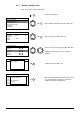
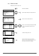
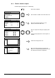
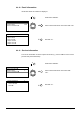
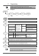

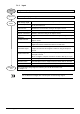
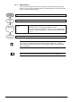
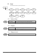
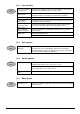
Table Of Contents
- 1 About this document
- /
- The information provided in this manual is a summary of the key procedures and functions required to assemble, install, operate, commission and repair the system.
- It is intended to provide experienced and qualified personnel a guide on the required processes.
- The technical manual applies to the Cerberus FIT fire control panel FC12x series.
- The information in this document is intended for the following target groups:
- The reference document has the following designation:
- ID_x_en_--
- x = version, en = English, -- = international
- The list below is used as a reference for the fire control panel FC12x and as a supplement to this document.
- Version
- Edition date
- Brief description
- 2 Safety regulations
- 3 System description
- /
- 4 Installation
- 5 Function overview
- 6 Operation
- AVC
- DIRECT
- Manned
- Unmanned
- The actual events will display all pending events.
- The panel is protected against unauthorized user operation.
- Therefore enter the password or turn the key switch (optional).
- The panel is protected against unauthorized user operation. Therefore enter the password or turn the key switch (optional).
- The alarm counter counts all fire alarms.
- All events such as alarm(s), fault(s), isolation(s), input(s) and output(s) activation are stored in a history log.
- Manual logout to access level 1.
- Each zone can be isolated individually.
- Enable the test mode for each zone.
- Disable outputs generally and / or individually.
- Information about the software is displayed.
- Exit with
. - Exit with
. - Exit with
. - 7 Programming
- Input customer text for:
- 8 Tool function
- 1. Start the Hyper Terminal and enter an appropriate name.
- 2. Select communication port.
- /
- Make sure your PC is connected to the FDUZ22x box and the driver is installed.
- /Make sure your PC is connected to the FDUZ22x box and the driver is installed.Check the communication port on the device manager.
- /
- /
- 1. Select the following option on the panel.
- 2. Enable the Hyper Terminal to receive data.
- /
- /
- /
- /
- /
- 1. Select the following option on the panel.
- 2. Enable the hyper terminal to receive data.
- /
- /
- /
- /
- /
- 1. Select the following option on the panel..
- 2. Enable the hyper terminal to 'Send file'.
- /
- /
- /
- 1. Click
. - 2. Select the folder 'Settings' and click 'ASCII Setup'.
- 5. PC will display as below. Press '2'.
- 6. 'CC…' shows the connection is established and ready for transfer.
- /
- /
- /
- 9 Commissioning
- 10 Maintenance
- 11 Battery capacity
- 12 Trouble shooting
- 13 Components and spare parts
- 14 Disposal and environmental protection
- Appendix A: Site configuration, Factory Setting
- Appendix B: Switch mains to AC 115 V
- Appendix C: History log

54
A6V10393190_j_en_--
6.4.10 Panel information
Information about the software is displayed.
Push button <MENU>.
Select ‘Panel information’ and confirm with <ok>.
Exit with <C>.
6.4.11 Service information
The service information is shown in quiescent mode (e.g. contact address of the service
provider and panel information).
Push button <MENU>.
Select ‘Panel information’ and confirm with
<ok>.
Exit with <C>.
C
Service information 2
xxxxxx FC12X
xxxxxx
ok
Menu 2
Panel information
Alarm counter 1
Service information
C
Panel information 2
Type: FC124-ZA
App: 01.00.19
Boot: 01.00.04
Output card 1
Output card 2
Output card
3
ok
Menu 2
Panel information
Alarm counter 0001
Service information