
Technical Manual
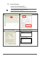
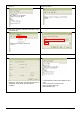
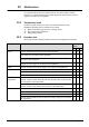
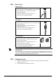
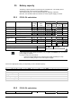
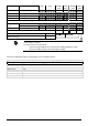
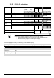
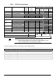
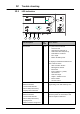
Table Of Contents
- 1 About this document
- /
- The information provided in this manual is a summary of the key procedures and functions required to assemble, install, operate, commission and repair the system.
- It is intended to provide experienced and qualified personnel a guide on the required processes.
- The technical manual applies to the Cerberus FIT fire control panel FC12x series.
- The information in this document is intended for the following target groups:
- The reference document has the following designation:
- ID_x_en_--
- x = version, en = English, -- = international
- The list below is used as a reference for the fire control panel FC12x and as a supplement to this document.
- Version
- Edition date
- Brief description
- 2 Safety regulations
- 3 System description
- /
- 4 Installation
- 5 Function overview
- 6 Operation
- AVC
- DIRECT
- Manned
- Unmanned
- The actual events will display all pending events.
- The panel is protected against unauthorized user operation.
- Therefore enter the password or turn the key switch (optional).
- The panel is protected against unauthorized user operation. Therefore enter the password or turn the key switch (optional).
- The alarm counter counts all fire alarms.
- All events such as alarm(s), fault(s), isolation(s), input(s) and output(s) activation are stored in a history log.
- Manual logout to access level 1.
- Each zone can be isolated individually.
- Enable the test mode for each zone.
- Disable outputs generally and / or individually.
- Information about the software is displayed.
- Exit with
. - Exit with
. - Exit with
. - 7 Programming
- Input customer text for:
- 8 Tool function
- 1. Start the Hyper Terminal and enter an appropriate name.
- 2. Select communication port.
- /
- Make sure your PC is connected to the FDUZ22x box and the driver is installed.
- /Make sure your PC is connected to the FDUZ22x box and the driver is installed.Check the communication port on the device manager.
- /
- /
- 1. Select the following option on the panel.
- 2. Enable the Hyper Terminal to receive data.
- /
- /
- /
- /
- /
- 1. Select the following option on the panel.
- 2. Enable the hyper terminal to receive data.
- /
- /
- /
- /
- /
- 1. Select the following option on the panel..
- 2. Enable the hyper terminal to 'Send file'.
- /
- /
- /
- 1. Click
. - 2. Select the folder 'Settings' and click 'ASCII Setup'.
- 5. PC will display as below. Press '2'.
- 6. 'CC…' shows the connection is established and ready for transfer.
- /
- /
- /
- 9 Commissioning
- 10 Maintenance
- 11 Battery capacity
- 12 Trouble shooting
- 13 Components and spare parts
- 14 Disposal and environmental protection
- Appendix A: Site configuration, Factory Setting
- Appendix B: Switch mains to AC 115 V
- Appendix C: History log

74
A6V10393190_j_en_--
10 Maintenance
It is assumed that the site was commissioned in accordance with the existing
directives, i.e. all functions have been tested and the site data has been saved or
logged to the table 'site configuration'.
10.1 Preparatory work
Inform the system owner of the scope and expected duration of work.
Disable the following system components as needed:
Alarm transmission (log out on the receiving centre)
Fire controls and sounder lines
Extinguishing stations
10.2 Function test
We recommend the following schedule. However, local regulations have priority.
Function Activity
Interval in
years
1 2 5
Zones Activate all automatic detectors and all manual call points. X
Activate a detector or manual call point per zone and verify zone assignment
and if usage is in accordance with regulations.
X
Check all detectors and manual call points for soiling and verify if usage is in
accordance with regulations.
X
Activate a fault, short circuit and open line, for each zone and verify zone
assignment and if usage is in accordance with regulations.
X
Inputs Activate each input and verify if usage is in accordance with regulations. X
Outputs Check sounder controls and all acoustic alarm devices. X
Activate fire outputs and check if usage is in accordance with regulations. X
Activate alarm and fault dialer and check the transmission. X
Alarm
organization
Mode Manned
Activate a detector and manual call point and check the timer V1 and V2 and
the transmission of the alarm dialer.
X
Mode Unmanned
Activate a detector and check the transmission of the alarm dialer.
X
Panel Check date and time. X
Check the display and LEDs. X
Check earth connections. X
Activate mains and battery fault condition and verify if usage is in accordance
with regulations.
X