
Technical Manual
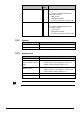
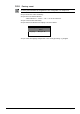
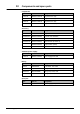
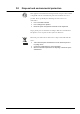
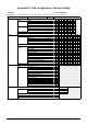
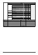
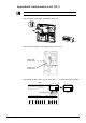
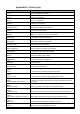
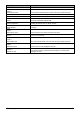

Table Of Contents
- 1 About this document
- /
- The information provided in this manual is a summary of the key procedures and functions required to assemble, install, operate, commission and repair the system.
- It is intended to provide experienced and qualified personnel a guide on the required processes.
- The technical manual applies to the Cerberus FIT fire control panel FC12x series.
- The information in this document is intended for the following target groups:
- The reference document has the following designation:
- ID_x_en_--
- x = version, en = English, -- = international
- The list below is used as a reference for the fire control panel FC12x and as a supplement to this document.
- Version
- Edition date
- Brief description
- 2 Safety regulations
- 3 System description
- /
- 4 Installation
- 5 Function overview
- 6 Operation
- AVC
- DIRECT
- Manned
- Unmanned
- The actual events will display all pending events.
- The panel is protected against unauthorized user operation.
- Therefore enter the password or turn the key switch (optional).
- The panel is protected against unauthorized user operation. Therefore enter the password or turn the key switch (optional).
- The alarm counter counts all fire alarms.
- All events such as alarm(s), fault(s), isolation(s), input(s) and output(s) activation are stored in a history log.
- Manual logout to access level 1.
- Each zone can be isolated individually.
- Enable the test mode for each zone.
- Disable outputs generally and / or individually.
- Information about the software is displayed.
- Exit with
. - Exit with
. - Exit with
. - 7 Programming
- Input customer text for:
- 8 Tool function
- 1. Start the Hyper Terminal and enter an appropriate name.
- 2. Select communication port.
- /
- Make sure your PC is connected to the FDUZ22x box and the driver is installed.
- /Make sure your PC is connected to the FDUZ22x box and the driver is installed.Check the communication port on the device manager.
- /
- /
- 1. Select the following option on the panel.
- 2. Enable the Hyper Terminal to receive data.
- /
- /
- /
- /
- /
- 1. Select the following option on the panel.
- 2. Enable the hyper terminal to receive data.
- /
- /
- /
- /
- /
- 1. Select the following option on the panel..
- 2. Enable the hyper terminal to 'Send file'.
- /
- /
- /
- 1. Click
. - 2. Select the folder 'Settings' and click 'ASCII Setup'.
- 5. PC will display as below. Press '2'.
- 6. 'CC…' shows the connection is established and ready for transfer.
- /
- /
- /
- 9 Commissioning
- 10 Maintenance
- 11 Battery capacity
- 12 Trouble shooting
- 13 Components and spare parts
- 14 Disposal and environmental protection
- Appendix A: Site configuration, Factory Setting
- Appendix B: Switch mains to AC 115 V
- Appendix C: History log

84
A6V10393190_j_en_--
14 Disposal and environmental protection
This equipment is manufactured using materials and procedures which
comply with current environmental protection standards as best as
possible. More specifically, the following measures have been
undertaken:
Use of reusable materials
Use of halogen-free plastics
Electronic parts and synthetic materials can be separated
Larger plastic parts are labelled according to ISO 11469 and ISO 1043.
The plastics can be separated and recycled on this basis.
Electronic parts and batteries must not be disposed of with domestic
waste.
Take electronic parts and batteries to local collection points or
recycling centre.
Contact local authorities for more information.
Observe national requirements for disposing of electronic parts
and batteries.