
Technical Manual
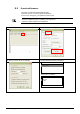

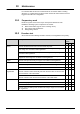
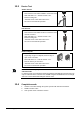
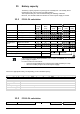
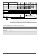
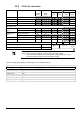
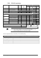
Table Of Contents
- 1 About this document
- /
- The information provided in this manual is a summary of the key procedures and functions required to assemble, install, operate, commission and repair the system.
- It is intended to provide experienced and qualified personnel a guide on the required processes.
- The technical manual applies to the Cerberus FIT fire control panel FC12x series.
- The information in this document is intended for the following target groups:
- The reference document has the following designation:
- ID_x_en_--
- x = version, en = English, -- = international
- The list below is used as a reference for the fire control panel FC12x and as a supplement to this document.
- Version
- Edition date
- Brief description
- 2 Safety regulations
- 3 System description
- /
- 4 Installation
- 5 Function overview
- 6 Operation
- AVC
- DIRECT
- Manned
- Unmanned
- The actual events will display all pending events.
- The panel is protected against unauthorized user operation.
- Therefore enter the password or turn the key switch (optional).
- The panel is protected against unauthorized user operation. Therefore enter the password or turn the key switch (optional).
- The alarm counter counts all fire alarms.
- All events such as alarm(s), fault(s), isolation(s), input(s) and output(s) activation are stored in a history log.
- Manual logout to access level 1.
- Each zone can be isolated individually.
- Enable the test mode for each zone.
- Disable outputs generally and / or individually.
- Information about the software is displayed.
- Exit with
. - Exit with
. - Exit with
. - 7 Programming
- Input customer text for:
- 8 Tool function
- 1. Start the Hyper Terminal and enter an appropriate name.
- 2. Select communication port.
- /
- Make sure your PC is connected to the FDUZ22x box and the driver is installed.
- /Make sure your PC is connected to the FDUZ22x box and the driver is installed.Check the communication port on the device manager.
- /
- /
- 1. Select the following option on the panel.
- 2. Enable the Hyper Terminal to receive data.
- /
- /
- /
- /
- /
- 1. Select the following option on the panel.
- 2. Enable the hyper terminal to receive data.
- /
- /
- /
- /
- /
- 1. Select the following option on the panel..
- 2. Enable the hyper terminal to 'Send file'.
- /
- /
- /
- 1. Click
. - 2. Select the folder 'Settings' and click 'ASCII Setup'.
- 5. PC will display as below. Press '2'.
- 6. 'CC…' shows the connection is established and ready for transfer.
- /
- /
- /
- 9 Commissioning
- 10 Maintenance
- 11 Battery capacity
- 12 Trouble shooting
- 13 Components and spare parts
- 14 Disposal and environmental protection
- Appendix A: Site configuration, Factory Setting
- Appendix B: Switch mains to AC 115 V
- Appendix C: History log

A6V10393190_j_en_-- 73
9 Commissioning
Planning
Assign the field devices to the floor plan as per local regulations.
Document the panel parameters (see Appendix A).
Calculate battery standby time (see chapter 11).
Field installation
Install detection lines (detectors and manual call points) and terminate with EOL
element.
Install control (sounder) lines and terminate with EOL element.
Panel installation
Fire control panel must be mounted.
Connect all detection lines or terminate with EOL element.
Connect all control lines or terminate with EOL element.
Connect alarm and fault dialer.
Inscription stripes must be inserted for zone ind. field (optional).
Switch off the main supply fuse AC 230 V.
Connect the power cable and check the earth connection.
Switch on the main supply fuse AC 230 V.
Place and connect battery.
Fill in and place the provided label at the top, right-hand side of the housing.
Programming
Initial start-up of the panel.
Program the system and resolve the faults.
Function test
Initiate lamp test and check all LED, internal buzzer.
Test each device (Detector, MCP, etc.) individually and check the correctness of
the system behavior in terms of outputs (e.g. Sounder, Fire output, etc.).
Test fire and fault transmission.
Make sure that the panel is in normal operation, the buzzer and all system parts are
enabled.
The system can now be handed over to the customer.
Warning Pay attention to external voltage (AC 230 V)!