
Technical Manual
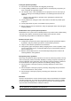
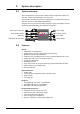
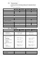
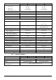

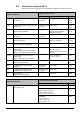
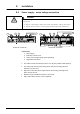
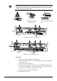
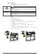
Table Of Contents
- 1 About this document
- /
- The information provided in this manual is a summary of the key procedures and functions required to assemble, install, operate, commission and repair the system.
- It is intended to provide experienced and qualified personnel a guide on the required processes.
- The technical manual applies to the Cerberus FIT fire control panel FC12x series.
- The information in this document is intended for the following target groups:
- The reference document has the following designation:
- ID_x_en_--
- x = version, en = English, -- = international
- The list below is used as a reference for the fire control panel FC12x and as a supplement to this document.
- Version
- Edition date
- Brief description
- 2 Safety regulations
- 3 System description
- /
- 4 Installation
- 5 Function overview
- 6 Operation
- AVC
- DIRECT
- Manned
- Unmanned
- The actual events will display all pending events.
- The panel is protected against unauthorized user operation.
- Therefore enter the password or turn the key switch (optional).
- The panel is protected against unauthorized user operation. Therefore enter the password or turn the key switch (optional).
- The alarm counter counts all fire alarms.
- All events such as alarm(s), fault(s), isolation(s), input(s) and output(s) activation are stored in a history log.
- Manual logout to access level 1.
- Each zone can be isolated individually.
- Enable the test mode for each zone.
- Disable outputs generally and / or individually.
- Information about the software is displayed.
- Exit with
. - Exit with
. - Exit with
. - 7 Programming
- Input customer text for:
- 8 Tool function
- 1. Start the Hyper Terminal and enter an appropriate name.
- 2. Select communication port.
- /
- Make sure your PC is connected to the FDUZ22x box and the driver is installed.
- /Make sure your PC is connected to the FDUZ22x box and the driver is installed.Check the communication port on the device manager.
- /
- /
- 1. Select the following option on the panel.
- 2. Enable the Hyper Terminal to receive data.
- /
- /
- /
- /
- /
- 1. Select the following option on the panel.
- 2. Enable the hyper terminal to receive data.
- /
- /
- /
- /
- /
- 1. Select the following option on the panel..
- 2. Enable the hyper terminal to 'Send file'.
- /
- /
- /
- 1. Click
. - 2. Select the folder 'Settings' and click 'ASCII Setup'.
- 5. PC will display as below. Press '2'.
- 6. 'CC…' shows the connection is established and ready for transfer.
- /
- /
- /
- 9 Commissioning
- 10 Maintenance
- 11 Battery capacity
- 12 Trouble shooting
- 13 Components and spare parts
- 14 Disposal and environmental protection
- Appendix A: Site configuration, Factory Setting
- Appendix B: Switch mains to AC 115 V
- Appendix C: History log

A6V10393190_j_en_-- 19
To avoid the risk of a connected wire become loose and can come in contact with the
mains terminal, a single wire must not be so long that it can come into contact with the
mains terminal or tie at least two such wires together so that the free end of a single
wire cannot reach the mains terminal!
FC123-ZA / FC124-ZA
fixing mains wire
Strip the insulation from the
wire
FC121-ZA / FC122-ZA secure wires
FC123-ZA / FC124-ZA secure wires
Explanation
5. Fixing cables and removing the outside isolation.
6. Lay the mains cable along the left side and signal and control lines to the right
side of the housing.
7. Fix the mains wire with cable ties.
8. Insulate the mains, signal and control lines wires as needed and connect it to
the terminals according to the pin assignment specified in chapter 4. Use mains
cable with cross section of 3*1.5 mm
2
up to 3*2.5 mm
2
.
9. Fix the signal and control lines with cable ties.
10. Shield connection terminal.
5 mm
5
7
5 mm
8
9
6
6
7
10
7
6
9
6
10