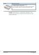
Cerberus™ PRO Fire control panel FC723 Modular, pre-assembled fire control panel with integrated, user-friendly operating unit for gradual migration to Cerberus PRO. ● ● ● ● ● ● ● ● ● ● ● A6V10379246_i_en_-2021-10-22 Fire control panel for max.
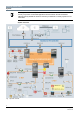
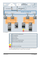
Features and Functions System The diagrams have been simplified and do not include additional network hardware or security components. Permissible applications are described in the A6V101039439 Network Security Guidelines document. Contact your Siemens IT security expert for more information. System overview Fig.
1 Remote access with Cerberus-Remote 2 FS cloud applications 3 Customer network 4 Management platform 5 Remote access to management platform 6 Remote access with Cerberus Mobile 7 Router + firewall + virtual private network 8 Fire damper with actuator Transmission of a fault signal Transmission of an alarm signal You will find a detailed labeled version of the diagram above along with further information in the A6V10332842 planning guide, see chapter 'Product documentation'.
Networking of fire control panels The diagrams have been simplified and do not include additional network hardware or security components. Permissible applications are described in the A6V101039439 Network Security Guidelines document. Contact your Siemens IT security expert for more information. Up to 32 control panels and terminals can be linked to form one C-WEB network. If the CWEB network is connected to a danger management system via BACnet, up to 16 control panels and terminals can be networked.
Fig. 3: Backbone 1 Remote access with Cerberus-Remote 2 FS cloud applications 3 Customer network 4 Management platform 5 Remote access to management platform 6 Remote access with Cerberus Mobile 7 Router + firewall + virtual private network Transmission of a fault signal Transmission of an alarm signal You will find a detailed labeled version of the diagram above along with further information in the A6V10332842 planning guide, see chapter 'Product documentation'.
Control panels General features and functions ● Fast Ethernet interface for a heterogeneous network ● Processes signals from the detector series Cerberus PRO FD720 as well as from earlier detector series ● Interface to Siemens danger management system ● Slots for RS232 and RS485 serial interfaces ● Floor repeater displays, terminals and alarm devices on the C-NET detector line with power supply via C-NET ● All detector lines are monitored for ground faults.
Control panel-specific features From IP8, the fire control panels can be ordered with a periphery board with a 0.5 A or 1.5 A output current per C-NET line. To convert existing fire control panels, the periphery board with 1.5 A per C-NET line can be ordered separately.
FH7203-Z3 Housing (Comfort) ● ● ● ● Empty housing for free use 430 x 796 x 165 mm E.g., for extra batteries, operating add-ons, or event printers Space for the following battery configurations: – 2x FA2005-A1 (17 Ah) or ● FH7205-Z3 – 2x BAT12-25 (25 Ah) The mounting kit for the batteries FHA2061-A1 must be ordered separately. Housing (Large) ● ● ● ● Empty housing for free use 430 x 796 x 265 mm E.g.
DL3750+ Matrix printer (external) ● ● ● ● External matrix printer recommended by Siemens Supports monitoring for printing faults Can be controlled via the RS232 module FCA2001-A1 (order separately) Can be controlled via Ethernet via the print server PS104 from SEH Use For medium-sized applications, e.g., for industrial plants, regional banks, or office complexes. As part of a modernization process, for a gradual and seamless transition from older systems to Cerberus PRO.
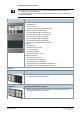
Design Function elements Operating unit The following elements are available on the operating unit: ● CPU module and electronics ● Ethernet connection ● Slots for RS232 and RS485 modules and network modules (SAFEDLINK) ● Space for 'Kaba' or 'nordic' key switch ● Space for event printer (depending on version) ● Peripheral data bus connection for optional LED modules Periphery board From IP8, the fire control panels can be ordered with a periphery board with a 0.5 A or 1.5 A output current per C-NET line.
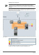
Setup Fig. 4: Layout of FC723 Position Designation Type Comment Items 1–6: Basic equipment. The periphery board (2 loops, P) can be ordered separately to convert the station to the 1.5 A C-NET line. Basic equipment 1 Housing (Comfort) FH7203-Z3 2 Periphery board (2 loops) FCI2002-A1 Periphery board (2 loops, P) FCI2023-A1 3 Power supply (SV 24 V-150 W) V24230-Z6-A5 4 Mains terminals on TS35 DIN rail - Space for socket, relay modules, etc.
Position Designation Type Comment Extensions (3) Power supply kit (150 W, B) FP2005-A1 Additional power supply for retrofitting (no diagram) 8 Relay module Z3B171 Relay for fire controls 9 Event printer FTO2001-A1 For logging events 10 Key switch (Kaba) FTO2005-C1 For operating access authorization Key switch (nordic) FTO2006-B1 11 Mounting plate FHA2007-A1 e.g.
Position Designation Type Comment 22 License key Sx FCA20xx For special functions 23 Cable kit (communication) FCA2014-A1 For flexible connections running to the modules on the operating unit Repeater (SAFEDLINK) FN2002-A1 Not in overview, as not an installation part. For extending the system bus C-WEB from 1000 m to 2000 m between two stations. Max. 1x repeater (SAFEDLINK) between two stations.
Type Overview Housing (Comfort) Type FC723-ZA Number of C-NET addresses 756 Loops (with loop extension) or 2 (4) Stubs (with loop extension) 4 (8) Power supply 150 W Max. battery capacity 25 Ah Max.
Details for ordering Control panel Type Designation Weight Order number FC723-ZA Fire control panel (modular) 16.495 kg S54400-C143-A1 Type Designation Weight Order number FCA2001-A1 RS232 module (isolated) 0.033 kg A5Q00005327 FCA2002-A1 RS485 module (isolated) 0.027 kg A5Q00009923 FCA2005-A1 Sounder module 0.100 kg A5Q00014866 FCA2014-A1 Cable kit (communication) 0.126 kg A5Q00023027 FCI2003-A1 Loop extension (C-NET) 0.
Type Designation Weight Order number FTO2001-A1 Event printer 0.141 kg A5Q00010126 - Spare printer reels (10 reels) 0.090 kg A5Q00017619 FTO2005-C1 Key switch (Kaba) 0.083 kg A5Q00010113 FTO2006-B1 Key switch (nordic) 0.046 kg A5Q00010129 Z3B171 Relay module 250 V AC / 10 A (1 relay) 0.042 kg 4843830001 Auxiliary power supply Type Designation Weight Order number FP2004-A1 Power supply kit (150 W, A) for ENcompliant installation in empty housing 1.
Batteries Type Designation Weight Order number FA2005-A1 Battery (12 V, 17 Ah, VdS) 5.700 kg A5Q00019677 BAT12-25 Battery (12 V, 25 Ah, VdS) 7.8 kg S54302-Z102-A1 FA2007-A1 Battery (12 V, 45 Ah, VdS) 14.500 kg A5Q00022897 FA2008-A1 Battery (12 V, 65 Ah, VdS) 21.300 kg A5Q00019357 FHA2061-A1 Mounting kit for batteries ‒ S54400-B91-A1 Type Designation Weight Order number FCA2033-A1 License key (S1) 0.010 kg S54400-P154-A1 FCA2034-A1 License key (S2) 0.
Product documentation Title Document ID System documentation System description A6V10210355 Product data A6V10210368 Planning A6V10210362 Mounting/Installation A6V10210390 System data sheet FS720 – Fire detection system A6V10227649 Data sheets FC721 - fire control panel A6V10203220 FC722 - fire control panel A6V10206525 FC723 - fire control panel for modernization A6V10379246 FC724 - fire control panel A6V10207176 FC726 - fire control panel (modular) A6V10263277 FT724 - fire terminal
Technical data Fire control panel (modular)/(modular, P) FC723 in housing (Comfort) Supply Inputs / outputs Mains voltage AC 115 / 230 V +10/-15 % Power supply 150 W Operating voltage DC 21…28.4 V Operating current Max. 5 A Battery capacity 2x 12 V, max. 25 Ah Battery monitoring Yes Network monitoring Yes Connectable detector series Cerberus PRO Other addressable detectors which can be connected SynoLOOP Number of addresses Max.
Fire control panel (modular)/(modular, P) FC723 in housing (Comfort) Additional I/O cards: Interfaces Ambient conditions Mechanical data ● Programmable 12x configurable inputs/outputs 2x supply outputs 24 V ● Horn/monitored 8x horn output monitored ● RT 1x alarm relay output 1x fault relay output 1x voltage output 24 V 2x GPIO 1x fault output monitored 2x configurable output monitored Operating unit Integrated Slots for serial interfaces RS232, RS485 2 Slots for network modules 2 Slot for
Issued by Siemens Switzerland Ltd Smart Infrastructure Global Headquarters Theilerstrasse 1a CH-6300 Zug +41 58 724 2424 www.siemens.com/buildingtechnologies Document ID A6V10379246_i_en_-- Edition 2021-10-22 © Siemens Switzerland Ltd, 2007 Technical specifications and availability subject to change without notice.