FCA2031-A1 Connection module (MoNet) Mounting Installation A6V10407860_a_en_-2014-04-29 Siemens Industry, Inc.
Legal notice Legal notice Technical specifications and availability subject to change without notice. © 2014 Copyright by Siemens Industry, Inc. Transmittal, reproduction, dissemination and/or editing of this document as well as utilization of its contents and communication thereof to others without express authorization are prohibited. Offenders will be held liable for payment of damages. All rights created by patent grant or registration of a utility model or design patent are reserved.
Table of contents 1 1.1 1.2 Connection module (MoNet) FCA2031-A1 .....................................................5 Description .......................................................................................................5 Views ...............................................................................................................6 1.3 Pin assignments ...............................................................................................6 1.3.1 Basic circuit diagram ........
1 Connection module (MoNet) FCA2031-A1 Description 4 Siemens Industry, Inc.
Connection module (MoNet) FCA2031-A1 Description 1 1 Connection module (MoNet) FCA2031-A1 1.1 Description The connection module (MoNet) FCA2031-A1 combines the degraded mode signals from the SAFEDLINK network and the peripheral data bus signals to the MoNet bus. The connection module (MoNet) is plugged into slot X13 of the main network module (SAFEDLINK) on the PMI & mainboard and connects the Ethernet switch (modular) to the system.
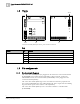
1 Connection module (MoNet) FCA2031-A1 Views 1.2 Views X401 X400 X402 X13 X1 Connection module (MoNet) FCA2031, print view front and back Key Element Des. Function Connector X1 Connector to X13 for the main network module (SAFEDLINK) on PMI & mainboard X13 Socket for the main network module (SAFEDLINK) X400 Connector to the peripheral data bus connection on PMI & mainboard X401 Socket for the peripheral data bus output X402 Socket for the MoNet bus 1.3 1.3.
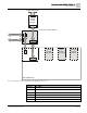
Connection module (MoNet) FCA2031-A1 Pin assignments 1 FCnet/SAFEDLINK X3 Main network module FN2001 X1 SAFEDLINK X400 Periphery Bus Connection module (MoNet) X13 X1 SAFEDLINK X401 MoNet Bus X400 Periphery Bus X402 FCA2031 Serial module SER_OPT1 Serial module SER_OPT2 Degrade network module X13 X13 PMI & Mainboard Basic circuit diagram of the connection module (MoNet) FCA2031-A1 Connector Description X13 Connector for the SAFEDLINK bus X1 Connector on the underside of the panel for
1 Connection module (MoNet) FCA2031-A1 Adjustment elements 1.4 Adjustment elements NOTICE Ground fault supervision When using the connection module (MoNet) FCA2031, the S33 'Earth-Fault Phy' switch on the PMI & mainboard must remain OFF. The ground fault detection already takes place via the MoNet bus. 1.5 Supply Supply outputs Connections Technical data Voltage System supply DC 24 V Current Normal operation 0 mA Maximum current 1 mA Peripheral data bus DC 20...30 V SAFEDLINK output DC 20...
FCC Statement 2 2 FCC Statement WARNING Installation and usage of equipment is not in accordance with instructions manual Radiation of radio frequency energy Interference to radio communications ● ● Install and use equipment in accordance with instructions manual. Read the following information. This equipment generates, uses, and can radiate radio frequency energy and if not installed and used in accordance with the instructions manual, may cause interference to radio communications.
Issued by Siemens Industry, Inc. Building Technologies Division 8 Fernwood Road Florham Park, NJ 07932 Tel. +1 973-593-2600 www.sbt.siemens.com/FIS Document ID A6V10407860_a_en_-- Edition 2014-04-29 © 2014 Siemens Industry, Inc. Technical specifications and availability subject to change without notice. SAP order no.