
Data Sheet for Product


Siemens
Smart Infrastructure – Building Products
–5–
usa.siemens.com/fire
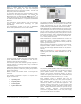
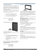
Remote Display Terminals (with RS─485 interface)
The Remote Display Terminals (Models FT2014-U2 / R2 and
FT2015-U2 / R2) are LED / LCD units that show the existing
status of a Desigo 252 / 504-point system.
A Remote Annunciator (Model FSD901-U2 / R2) is used for
the Desigo 50-point FACP (Model FC2005).
A LED will illuminate for any given Alarm, Supervisory and
Trouble Desigo-system event. An LCD screen will give details
of the event in alphanumeric form. The display screen can
be scrolled to reveal additional events. Optional remote-
system-control capabilities are also available.
When an event has been triggered to the Desigo panel, the
LCD screen will show the following:
▪ Event type and zone
▪ Time of the event [only possible in a menu-driven
function]
▪ Custom message for that zone
▪ Usage of the zone
▪ ‘Unacknowledged’ or ‘Acknowledged’ event
The display has a backlight feature that operates upon
receiving any event information or when any operator
buttons are pressed.
The Model FT2014-series display terminal has a button used
to silence the local sounder. Meanwhile, the Model FT2015-
series display terminal has three (3) control buttons for
‘acknowledging’ events; silencing audible circuits and
resetting the system. Additionally, there are three (3) user-
programmable buttons available. The Model FT2015-series
has a key switch that enables the control buttons to operate.
Model FT2014 / 2015 supports Canada's 8-event display
mode requirement.
The remote display terminals are remotely connected to the
Desigo FACP, via the RS─485 interface. The Model FC2025
and FC2050 Desigo panels require the Model FCA2016-U1
RS─485 module to provide communication to the remote
display terminals. Model FCA2016-U1 supports Style 4 or
Style 6 wiring. Up to eight (8) modules can be supported on
a RS─485 bus.
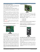
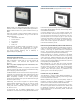
Leased-Line / City-Tie Module
Leased-Line / City-Tie Module (Cont.)
The Leased-Line / City-Tie module (Model FCI2020-U1) is
used as an optional module, providing a local-energy output
for municipal call-box connection.
Model FCI2020-U1 also gives a reverse-polarity output for
leased-line connection. Model FCI2020-U1 is installed on
the periphery board for Models FC2025 and FC2050 FACPs,
respectively, but is installed on the back of the main board
of the Model FC2005 FACP.
When used for connection to a municipal call box, the city-
tie function supports Alarm-event transmission. When used
for leased-line connection, the module supports two (2)
leased telephone lines for transmitting Alarm, Trouble and
Supervisory events.
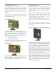
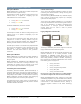
Single-Mode / Multi-Mode Fiber-Optic Module
The Single-Mode (Model FN2006-U1) / Multi-Mode (Model
FN2007-U1) fiber-optic interface module can be used to
transmit RS─485 communication for the Desigo Model
FC2025 and FC2050 (FACP), as well as the Model FT2050
Fire Terminal.
The single-mode / multi-mode fiber-optic module provides
C-net peer-to-peer network communication between the
Desigo 252-point and 504-point fire systems.
Models FN2006-U1 / FN2007-U1 require 24 Volts DC
[nominal] power, and the Models FC2025 or FC2050 FACP
serve as the source for this power specification. Models
FN2006-U1 / FN2007-U1 can also be powered from any UL
Listed, regulated 24VDC power supply, such as The
Distributed Power Module & NAC Extender.
Models FN2006-U1 / FN2007-U1 can be mounted in a
Desigo one-height-unit or two-height unit enclosure, and
can operate in a daisy-chain configuration.
Two (2), high-quality duplex 9/125 fiber-optic cables and ST-
style fiber connectors are used for connection between
single-mode fiber-optic modules. The duplex fiber-optic
cable has two (2) cables in a single shield that is similar to
an electrical zip cord. When using single-mode fiber, each
segment of the fiber network can be up to almost 10 miles
(16.1 km).
For ‘Class B’ installations, each FACP or terminal at either end
of the daisy chain use one (1) duplex cable for connection to
the next networked panel or terminal. FACPs or terminals
within the daisy chain require two (2) duplex cables: one
(1) duplex cable for connection to the previous FACP, and
one (1) duplex cable for connection to the next FACP.
For ‘Class A’ installations, each FACP or terminal requires two
(2) duplex cables: one (1) duplex cable for connection to
the previous FACP, and one (1) duplex cable for connection
to the next FACP.
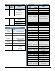
252 / 504-point System Components
Model
FCI2020-U1
Model
FT2015-U2