FDCL221-M Multi line separator module Technical Manual A6V10224006_g_en_-2018-10-25 Building Technologies Control Products and Systems
Imprint Imprint Technical specifications and availability subject to change without notice. Transmittal, reproduction, dissemination and/or editing of this document as well as utilization of its contents and communication thereof to others without express authorization are prohibited. Offenders will be held liable for payment of damages. All rights created by patent grant or registration of a utility model or design patent are reserved. Issued by: Siemens Switzerland Ltd.
Table of contents 1 1.1 1.2 1.3 1.4 About this document ............................................................................. 5 Applicable documents ................................................................................. 7 Download center ......................................................................................... 8 Technical terms .......................................................................................... 8 Revision history ....................................
6 Commissioning ...................................................................................34 7 Maintenance / Troubleshooting .............................................................35 8 8.1 8.2 8.3 Specifications .....................................................................................36 Technical data ........................................................................................... 36 Dimensions .......................................................................
About this document Applicable documents 1 1 About this document ● Specialist electrical engineering knowledge is required for installation. ● Only an expert is permitted to carry out installation work. Incorrect installation can take safety devices out of operation unbeknown to a layperson. Goal and purpose This document contains all information on the multi line separator module FDCL221-M. Consistent compliance with the instructions guarantees correct and safe use.
1 About this document Applicable documents Target groups The information in this document is intended for the following target groups: Target group Activity Qualification Product Manager ● ● ● Project Manager ● ● Project engineer ● ● ● Installation personnel ● ● Maintenance personnel ● ● ● Is responsible for information passing between the manufacturer and regional company. Coordinates the flow of information between the individual groups of people involved in a project.
About this document Applicable documents 1 Date format The date format in the document corresponds to the recommendation of international standard ISO 8601 (format YYYY-MM-DD). Conventions for text marking Markups Special markups are shown in this document as follows: ⊳ Requirement for a behavior instruction 1. 2.
1 About this document Download center 1.2 Download center You can download various types of documents, such as data sheets, installation instructions, and license texts via the following Internet address: https://siemens.com/bt/download l Enter the document ID in the search field. You will also find information about search variants and links to mobile applications (apps) for various systems on the home page. 1.
About this document Revision history 1 1.4 Revision history The reference document's version applies to all languages into which the reference document is translated. The first edition of a language version or a country variant may, for example, be version 'd' instead of 'a' if the reference document is already this version.
2 Safety Safety instructions 2 Safety 2.1 Safety instructions The safety notices must be observed in order to protect people and property. The safety notices in this document contain the following elements: ● Symbol for danger ● Signal word ● Nature and origin of the danger ● Consequences if the danger occurs ● Measures or prohibitions for danger avoidance Symbol for danger This is the symbol for danger. It warns of risks of injury. Follow all measures identified by this symbol to avoid injury or death.
Safety Safety instructions 2 How risk of injury is presented Information about the risk of injury is shown as follows: WARNING Nature and origin of the danger Consequences if the danger occurs ● Measures / prohibitions for danger avoidance How possible damage to property is presented Information about possible damage to property is shown as follows: NOTICE Nature and origin of the danger Consequences if the danger occurs ● Measures / prohibitions for danger avoidance Building Technologies Fire Safety
2 Safety Safety regulations for the method of operation 2.2 Safety regulations for the method of operation National standards, regulations and legislation Siemens products are developed and produced in compliance with the relevant European and international safety standards.
Safety Safety regulations for the method of operation 2 Mounting, installation, commissioning and maintenance ● ● ● ● If you require tools such as a ladder, these must be safe and must be intended for the work in hand. When starting the fire control panel ensure that unstable conditions cannot arise. Ensure that all points listed in the 'Testing the product operability' section below are observed.
2 Safety Standards and directives complied with Disregard of the safety regulations Before they are delivered, Siemens products are tested to ensure they function correctly when used properly. Siemens disclaims all liability for damage or injuries caused by the incorrect application of the instructions or the disregard of danger warnings contained in the documentation.
Setup and function Overview 3 3 Setup and function 3.1 Overview Figure 1: Multi line separator module FDCL221-M The multi line separator module FDCL221M contains several separate line separators. Each line separator can detect short-circuits in the FDnet/C-NET and disconnect the detector line. The multi line separator module is intended to allow easier conversions from collective detector lines to the Sinteso/Cerberus fire detection system with the FDnet/C-NET bus system.
3 Setup and function Overview Applications ● ● If multiple sub-stubs are to be connected to a single point on the FDnet/C-NET detector line, either another FDnet/C-NET device or a line separator must be mounted between the sub-stubs. Time-optimized modernization of collective detector lines on the addressed FDnet/C-NET system.
Setup and function Setup 3 3.2 Setup 3.2.1 Overview 7 1 4 7 2 7 3 3 5 7 6 3 8 8 3 Figure 2: Overview of multi line separator module Building Technologies Fire Safety 1 Connector (20-pin) for sub-stub lines 5 Screw terminal for FDnet/C-NET detector line LINE 2 2 Module carrier 6 Screw terminal for FDnet/C-NET detector line LINE 1 3 Holes for mounting feet 7 Cable tie holder 4 Jumpers J1...
3 Setup and function Setup 3.2.2 Printed circuit board view 2 1 6 4 3 5 8 7 9 10 J1 J2 J3 J4 11 12 13 Figure 3: Printed circuit board view of multi line separator module 1 LED line separator 1 10 Jumpers J1...
Setup and function Function 3 3.2.4 Adjustment elements The multi line separator module has four jumpers, J1...J4. These jumpers can be used to configure whether the FDCL221-M is to be operated in one FDnet/C-NET loop or two FDnet/C-NET loops. Jumpers J1...J4 have the following two plug positions: 1-loop operation 2-loop operation 1 2 3 1 2 3 J1 J2 J3 J4 J1 J2 J3 J4 The jumpers are plugged on 1-loop operation when delivered. See also 2 Function [➙ 19] 3.
3 Setup and function Function 1-loop operation The multi line separator module is connected to a FDnet/C-NET loop. This is the default configuration of the multi line separator module when delivered.
Setup and function Behaviour in degraded mode 3 2-loop operation The multi line separator module can be connected to two separate FDnet/C-NET loops.
3 Setup and function Accessories 3.5 Accessories 3.5.1 Mounting foot FDCM291 ● ● ● ● For device mounting on a DIN rail TS35 Two mounting feet must always be used Compatible with: – Input module FDCI22x(-CN) – Input/output module FDCIO22x(-CN) – Output module FCA1209-Z1 – Multi line separator module FDCL221-M – Zone module, external powered FDCI223, FDCI723 – Sounder module FCA2005-A1 Order number: A5Q00003855 3.5.
Setup and function Accessories 3 3.5.3 Housing FDCH221 ● ● ● To protect against dust and wetness Compatible with: – Multi line separator module FDCL221-M – Input module FDCI22x(-CN) – Input/output module FDCIO22x(-CN) – Output module FCA1209-Z1 – Radio gateway FDCW241 – Zone module, external powered FDCI223, FDCI723 – Sounder module FCA2005-A1 Order number: S54312-F3-A1 See also 2 Mounting with housing FDCH221 [➙ 31] 3.5.4 M20 x 1.
3 Setup and function Accessories 3.5.6 Connection terminal DBZ1190-AB ● ● ● ● ● 24 | 42 Building Technologies Fire Safety Auxiliary terminal for connecting cables For T-branches of additional cabling, e.g., for cable shielding, detector heating units, sounder base, external alarm indicators, etc. For conductor cross-sections of 0.5…2.
Planning Accessories 4 4 Planning Unique detector line topology recognition is ensured if at least one device with a separating function is present between two sub-stub lines. In this case a line separator. Station FDCL221 FDCL221-M Figure 6: Line separator between two sub-stubs If several sub-stub lines are to be activated on one FDnet/C-NET loop, failure of large numbers of devices must be prevented in the event of a line short-circuit. In this regard the national regulations must be observed.
4 Planning Accessories Placing the multi line separator module FDCL221-M in intermediate distributors e.g.
Planning 4 Compatibility 4.1 Compatibility Compatible with control panels that support the FDnet/C-NET detector line. Detector line FC20xx FC72x FDnet X – X C-NET – X – 1 SIGMASYS AlgoRex 1 X FC360 – 1 – X With suitable line card X = compatible – = not compatible You will find detailed information in the 'List of compatibility'. Mixed operation with other devices on the same detector line is possible without restrictions.
4 Planning Environmental influences 4.4 Environmental influences If the devices are used in industrial applications, consultation with the project manager is required, since plastics do not withstand certain environmental conditions. The following factors must be taken into consideration: ● Chemicals ● Temperature ● Moisture The housing is made from plastic and the printed circuit board is sealed with wax for increased corrosion protection.
Mounting / Installation Mounting on U-rail or flat surface 5 5 Mounting / Installation The multi line separator module can be installed directly or in an additional housing. The additional housing FDCH221 must be ordered separately. See also 2 Housing FDCH221 [➙ 23] 5.
5 Mounting / Installation Removing from the U-rail Figure 9: Vertical or horizontal mounting on U-rail TS35 See also 2 Installation and connection diagram [➙ 32] 5.2 Removing from the U-rail Proceed as follows to remove the multi line separator module from the U-rail: 1. Place a screwdriver at a right angle between the mounting foot and the mounting surface of the U-rail. 2. Turn screwdriver to release mounting foot.
Mounting / Installation Mounting with housing FDCH221 5 5.3 Mounting with housing FDCH221 The multi line separator module can be installed in a separate housing FDCH221. The housing protects the multi line separator module from dirt and dust. Proceed as follows to mount the multi line separator module in housing FDCH221: 1. Break open required cable entries on housing. 2. Install housing on a flat surface. 3. Insert cables. If necessary, fasten the cables using the M20 x 1.
5 Mounting / Installation Installation and connection diagram 5.4 Installation and connection diagram ● Specialist electrical engineering knowledge is required for installation. ● Only an expert is permitted to carry out installation work. Incorrect installation can take safety devices out of operation unbeknown to a layperson.
Mounting / Installation Installation and connection diagram 1 Bare length for 20-pin connector 6 2-loop operation: FDnet/C-NET loop 2 2 Press screwdriver (width of blade 2.
6 Commissioning 6 Commissioning From a FDnet/C-NET communication point of view, the multi line separator module FDCL221-M is a line participant which, depending on the operation mode, occupies up to nine bus addresses and is visible in the line topology. Each individual line separator has its own bus address. The device is commissioned via the control panel. The exact procedure is described in the control panel documentation. Conduct a performance check once commissioning is complete.
Maintenance / Troubleshooting 7 7 Maintenance / Troubleshooting The multi line separator module is maintenance-free. It features a self-monitoring function and must be replaced if damaged.
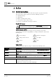
8 Specifications Technical data 8 Specifications 8.1 Technical data You will find information on approvals, CE marking, and the relevant EU directives for this device (these devices) in the following document(s); see 'Applicable documents' chapter: ● Document A6V10230308 Detector line Operating voltage DC 12…33 V Quiescent current: ● 1-loop operation 2.
Specifications Technical data Line separator (per separator) 8 Line voltage: ● Nominal DC 32 V (= Vnom) ● Minimum DC 12 V (= Vmin) ● Maximum DC 33 V (= Vmax) Voltage at which the separator opens: ● Minimum DC 7.5 V (= VSO min) ● Maximum DC 10.5 V (= VSO max) Permanent current when switches are closed Max. 1.5 A (= IC max) Switching current (e.g., in the event of a short-circuit) Max. 2 A (= IS max) Leakage current when switches are open Max.
8 Specifications Technical data Mechanical data Dimensions (L x W x H): ● Module FDCL221-M (without housing) 132 x 90 x 24 mm ● Housing FDCH221 207 x 119 x 50 mm Weight of module FDCL221-M 0.
Specifications Dimensions 8 8.2 Dimensions 132 102 132 24 36 90 Figure 14: Dimensions for different types of mounting without housing 207 50 119 Figure 15: Dimensions for housing FDCH221 8.3 Environmental compatibility and disposal This equipment is manufactured using materials and procedures which comply with current environmental protection standards as best as possible.
Index Index Numerics 1-loop operation All 9 line separators in one detector line .......... 19 2-loop operation 4 line separators each in one detector line ...... 19 A Application area Ambient conditions ......................................... 28 Approvals........................................................ 36 Attachment Screws ........................................................... 16 U-rail .............................................................. 16 C CE marking .....................
Index Building Technologies Fire Safety 41 | 42 A6V10224006_g_en_-2018-10-25
Issued by Siemens Switzerland Ltd Building Technologies Division International Headquarters Theilerstrasse 1a CH-6300 Zug +41 58 724 2424 www.siemens.com/buildingtechnologies Document ID: A6V10224006_g_en_-Edition: 2018-10-25 © Siemens Switzerland Ltd, 2009 Technical specifications and availability subject to change without notice.