
Installation Instructions

Siemens Siemens
Siemens Siemens
Siemens
IndustryIndustry
IndustryIndustry
Industry
,,
,,
,
Inc. Inc.
Inc. Inc.
Inc.
Building Building
Building Building
Building
TT
TT
T
ecec
ecec
ec
hnologies Dihnologies Di
hnologies Dihnologies Di
hnologies Di
visionvision
visionvision
vision
P/N 315-050716-1
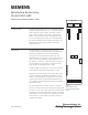
Model OCM-16RC
Output Control Module Ribbon Cable
Installation Instructions
INTRODUCTION The Model OCM-16RC Output Control Module Ribbon
Cable from Siemens Industry, Inc. is a remotely located,
general purpose output module. It provides sixteen
open collector outputs to drive LEDs, incandescent
lamps, or external relays. There is an additional output
for a local audible and two inputs for momentary lamp
test and local audible silence switches. The outputs are
programmed by inserting the OCM-16 in the Zeus
Programming Tool.
OPERATION The OCM-16RC is mounted in an enclosure that is
remotely located from the Main Panel. Communication
between the OCM and the NIC-C or DAC-NET is
through the Control Area Network (CAN) bus. Each
OCM-16RC has two 10 position rotary switches that are
used to set the board address on the CAN which is a
sub-address of the NIC-C or DAC-NET. The 16 outputs of
the OCM-16RC are controlled by messages received
from the NIC-C or DAC-NET over the CAN.
A CAN message can activate any or all of the 16 outputs
to drive LEDs, incandescent 24 Volt lamps or relays.
Whenever any of the outputs is activated, (LEDs, lamps
or relays ON) the local audible (if installed) will sound
until it is acknowledged by shorting position 19 and 20
on TB2. If the outputs are deactivated before the alarm
(local audible) is acknowledged, the alarm (local audible)
will cease to sound.
By shorting terminals 17 and 18, all LEDs or lamps will
turn on to confirm that they are working and automatically
will return to their normal state after a few seconds. Both
the lamp test and local audible silence switch on multiple
OCM-16RCs can be connected to a single switch, one for
each function. A single audible can also be used with
multiple OCM-16RCs.
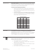
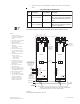
Figure 1
OCM-16RC Output
Control Module Ribbon
Cable
17 18 19 20 21 22 23 24
1
2
3
4
5
6
7
8
9
0
1
2
3
4
5
6
7
8
9
0
S1
1
5
3
7
2
6
4
8
S2
TB2
P2
P3
TB3
1
5
3
7
2
6
4
8
OCM-16RC
JP1
JP2
210
19
210
19
15
P1
26