
Installation Instructions

Installation Instructions
Model CXL-MP
Mounting Plate
Siemens Siemens
Siemens Siemens
Siemens
IndustryIndustry
IndustryIndustry
Industry
,,
,,
,
Inc. Inc.
Inc. Inc.
Inc.
Building Building
Building Building
Building
TT
TT
T
ecec
ecec
ec
hnologies Dihnologies Di
hnologies Dihnologies Di
hnologies Di
visionvision
visionvision
vision
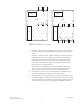
P/N 315-048596-7
INTRODUCTION Use the Model CXL-MP mounting plate from Siemens Industry, Inc., to upgrade
exisiting CXL Systems installed in Model EBX-1 backboxes to NCCNT-WAN Systems.
The CXL-MP accommodates COM-1 WAN System components. Additional COM-1
WAN component setup can be referenced in the FireFinder Network Command
Center Graphics Manual, P/N 315-049679.
With this conversion, the maximum battery size that can be used in the backbox is
31 AH. If a larger battery is required, use either a BB-55 or CAB-BATT battery box.
To convert an EBX-1 backbox from a CXL System to a COM-1 component system,
you must first disassemble the CXL and then assemble the COM-1. This two-part
procedure is described in detail below.
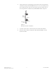
DISASSEMBLY OF CXL SYSTEM
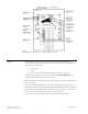
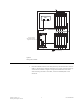
Refer to Figure 1 on page 2.
Remove all system power, first battery and then AC.
1. Disconnect the input and output power wires from the line filter.
The COM-1 WAN System uses batteries as a back-up power source. If a UPS was
used for the CXL System, disconnect it.
2. Disconnect the AC power wires from the CXA-1.
3. Disconnect all connections from the CXA-1 to the CXB-1. Remove and save
the hardware that secures the CXA-1 to the enclosure. Remove the CXA-1.
4. Disconnect the wiring to all modules in the CXB-1 and identify the wires.
Remove and save the hardware that secures the CXB-1 to the enclosure.
Remove the CXB-1.
5. Remove the batteries from the enclosure (if used).
6. Remove and save the hardware that secures the battery tray to the enclo-
sure. Remove the battery tray (if used).