
User Manual

Installation Instructions
Model FP2012-U1
300W Power Supply Module
A6V10334250_b_en_US
Siemens Industry, Inc.
Building Technologies Division
Florham Park, NJ
Siemens Canada Limited
Building Technologies Division
2 Kenview Boulevard
Brampton, Ontario L6T 5E4 Canada
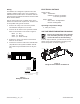
2. Place the FP2012-U1 housing over the four studs
provided in the enclosure indicated in the system
installation manual. (Refer to Figure 1 for a typical
example.) Note that depending on the enclosure, it
is possible to mount the FP2012-U1 in either a
horizontal or vertical position.
3. Using the lock nuts provided, secure the FP2012-U1
to the mounting studs of the enclosure.
FP2012-U1
FP2012-U1 Mounting
Studs (4 places)
Typical Enclosure
Figure 1
FP2012-U1 Mounting in Typical Enclosure
INTRODUCTION
The Model FP2012-U1 is a modular power supply that
provides primary regulated 24VDC power for normal
operation. The FP2012-U1 is rated 11.5A@24VDC and
regulation is under all load/line cases.
The module incorporates two 6.3A replaceable, non-
resettable slow-blow fuses on the primary input and
includes a built-in AC line filter for surge and noise
suppression. (Refer to Figure 3 for the location of the
fuses.) The FP2012-U1 mounts in a standard enclosure
or FHB2002-xx FS20 Backbox. A green LED illumi-
nates to indicate that the module is powered up.
There are no serviceable parts to be maintained.
INSTALLATION
Remove all system power before installa-
tion, first battery then AC. (To power up,
connect the AC first, then the battery.)
The installation kit for the FP2012-U1 includes the
following:
1 FP2012-U1 Power Supply Unit
4 #10 lock nuts
1 Installation Instruction
For 240VAC installation, reference the
Voltage Selector Switch on Figure 3
before installing the FP2012-U1 module.
Mounting
Mount the enclosure to the wall before mounting the
FP2012-U1 power supply to the enclosure.
1. Make sure that the dedicated circuit breaker for
the FP2012-U1 is turned off at the mains.