FT2080 Fire terminal (Touch) Mounting Installation A6V10462660_en--_c 2021-06-16 Smart Infrastructure
Imprint Imprint Technical specifications and availability subject to change without notice. Transmittal, reproduction, dissemination and/or editing of this document as well as utilization of its contents and communication thereof to others without express authorization are prohibited. Offenders will be held liable for payment of damages. All rights created by patent grant or registration of a utility model or design patent are reserved. Issued by: Siemens Switzerland Ltd.
Table of contents A6V10462660_en--_c 1 Setup of fire terminal (Touch) FT2080 ..................................................... 5 2 Installation in 19" pedestal housing of the FC2080................................. 7 3 Installation in housing (standard) ...........................................................10 4 Installation in rear panel (FT2080) FHA2039 ...........................................11 5 Installation in desktop housing (FT2080) FHA2040................................
| 24 A6V10462660_en--_c
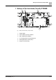
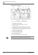
Setup of fire terminal (Touch) FT2080 1 1 Setup of fire terminal (Touch) FT2080 1 2 3 6 4 4 4 4 6 5 Fig.
1 Setup of fire terminal (Touch) FT2080 Arrangement of components Fig.
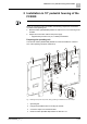
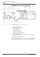
2 Installation in 19" pedestal housing of the FC2080 2 Installation in 19" pedestal housing of the FC2080 The installation instructions described below apply to all operating units. Before an operating terminal is installed, the following components must first be mounted on the operating unit.
2 Installation in 19" pedestal housing of the FC2080 5 2x fixing screw 6 PMI & mainboard FCM2027 7 Adapter for power supply (including ribbon cable) 8 Connector strip X3 peripheral data bus connection 1. Plug the network module (SAFEDLINK) (4) into connector X13 (3) of the operating unit (1). 2. Secure the module to mounting flange (2) with both screws (5). Ensure that it is secured correctly to avoid interrupts. 3.
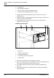
2 Installation in 19" pedestal housing of the FC2080 Wiring the fire terminal (Touch) 3 4 5 2 1 6 Fig.
3 Installation in housing (standard) 3 Installation in housing (standard) Fig.
4 Installation in rear panel (FT2080) FHA2039 4 Installation in rear panel (FT2080) FHA2039 The rear panel (FT2080) can be used for installation in a desk or installation in a third-party housing. Installing the rear panel (FT2080) in a third-party housing guarantees the required EMC protection.
4 Installation in rear panel (FT2080) FHA2039 Installing fire terminal board FTI2001 2 3 4 1 5 Fig. 9: Installing the fire terminal board in the rear cover (FT2080) 1 Rear panel (FT2080) FHA2039 2 Fire terminal board FTI2001 3 4x fixing screws 4 4x mounting holes 5 Threaded press-in sleeves in rear cover (FT2080) 1. Position the fire terminal board (2) in the rear panel (1) as shown. 2.
Installation in rear panel (FT2080) FHA2039 4 Wiring the fire terminal (Touch) When installing in a desktop that is thicker than 33 mm, the cables must be routed through the rectangular openings of the rear panel (FT2080), and not through the round cable breakthroughs. Fig.
4 Installation in rear panel (FT2080) FHA2039 1. Wire up the flat cable from the fire terminal board X3 to the PMI & mainboard X3. 2. Wire up the prefabricated cable of the supply from the EMC filter to the fire terminal board X7. 3. Wire up the external cables of the supply, the FCnet and the Ethernet cable through the cut-out in the desktop and the cable lead-throughs in the rear panel. Installing the fire terminal (Touch) 2 1 3 4 5 6 7 8 9 Fig.
Installation in rear panel (FT2080) FHA2039 4 1. Position the wired-up fire terminal (Touch) (1) on the rear panel (7) as shown. 2. Screw the four fixing screws (2) through the holes (3) to secure the fire terminal (Touch) (1) into the threaded holes (5) in the rear panel. Installing the rear cover (FT2080) in a desktop 3 1 2 4 5 7 6 Fig.
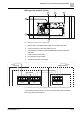
5 Installation in desktop housing (FT2080) FHA2040 5 Installation in desktop housing (FT2080) FHA2040 1 2 3 5 4 11 6 7 10 9 8 Fig.
5 Installation in desktop housing (FT2080) FHA2040 1. Remove the top of housing (1) by pushing the two tilting brackets (2) on the left and right inwards until you can lift off the top of housing. 2. Connect the ground connection as shown with clamping bracket (5) and M4 pan head screw (4). 3. Place the spacer sleeves (10) from below over the rubber feet (9). 4. Position the housing (3). 5. Place the washers (8) onto the rubber feet (9) inside the housing. 6.
5 Installation in desktop housing (FT2080) FHA2040 Installing fire terminal (Touch) FT2080 2 1 2 1 3 4 3 5 Fig. 15: Mounting in top of housing 1 Tilting brackets on left and right for fixing the top of the housing 2 2x fixing screws for tilting brackets and fire terminal 3 2x fixing screws for fire terminal 4 Fire terminal (Touch) FT2080 5 Top of desktop housing (FT2080) FHA2040 1. Place the fire terminal (4) in the top (5) of the desktop housing as shown. 2.
5 Installation in desktop housing (FT2080) FHA2040 Assembly of desktop housing (FT2080) 1 2 3 4 5 6 5 Fig. 16: Assembly of desktop housing 1 Fire terminal (Touch) FT2080 2 Top of desktop housing (FT2080) FHA2040 3 Tilting brackets on left and right for fixing the top of the housing 4 Guide cams on left and right for tilting brackets 5 2x threaded holes for fixing the top of the housing 6 Base of desktop housing 7 Fire terminal board FTI2001 1.
5 Installation in desktop housing (FT2080) FHA2040 1 2 3 1 4 Fig. 17: Securing the top of the desktop housing 1 Securing cap (scope of delivery) 2 Opening for fixing screw 3 Top of the desktop housing (Touch) 4 Fixing screw with securing device 1. To close the housing, tilt the top of the housing (3) onto the housing and secure the top to the housing using both screws (4). 2.
Installation in desktop housing (FT2080) FHA2040 5 Fire terminal wiring Fig.
6 Technical data 6 Technical data Supply input Display Interfaces Voltage DC 20…30 V Quiescent current (display illumination dimmed 15%) 390 mA Maximum current (display illumination 100% and lamp test active) 700 mA Screen size 12" Resolution 1280 x 800 pixels 2x slots for serial modules ● ● RS232 module for event printer RS485 module for ESPA-4.4.4 interface, FAT, FBF, UGA or remote EVAC-NL operation 2x slots for network modules (SAFEDLINK) ● Full functionality incl.
Technical data A6V10462660_en--_c 6 23 | 24
Issued by Siemens Switzerland Ltd Smart Infrastructure Global Headquarters Theilerstrasse 1a CH-6300 Zug +41 58 724 2424 www.siemens.com/buildingtechnologies A6V10462660_en--_c © Siemens Switzerland Ltd, 2015 Technical specifications and availability subject to change without notice.