
Operating Instructions

Installing
Installing the Power Module
5
40 | 118
Siemens A5E36496664A_f
Smart Infrastructure 2021-10-11
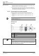
Connecting the motor cable to the variable speed drive
To connect the motor cable to the variable speed drive, proceed as follows:
1. Open the terminal covers (if fitted) of the variable speed drive.
2. Connect the motor at terminals U2, V2 and W2. Follow the instructions
pertaining to EMC-compliant wiring (Chapter EMC-compliant installation
(examples) [➙ 47]).
3. Connect the protective conductor of the motor to terminal PE of the variable
speed drive.
4. Close the terminal covers (if fitted) of the variable speed drive.
Connecting a motor cable to an induction motor
To connect the motor cable to an induction motor, proceed as follows:
1. Open the motor terminal box.
2. Connect the motor in either a star or delta connection. You can find further
information in the Operating Instructions for the Control Unit (A5E34257946B).
3. If you are using a shielded motor cable, you must do the following:
– Expose the shield of the motor cable in the area of the cable entry in the
terminal box.
– Attach the cable shield to the motor terminal box using a suitable screw
connection.
4. Close the motor terminal box.
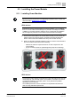
IP55 devices
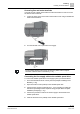
Overview
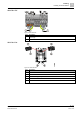
Figure 13: Connection of G120P IP55
Item Designation
1
Power Module
2
Sine-wave filter or dv/dt filter (optional)
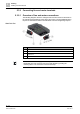
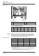
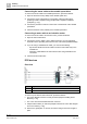
To connect up the line and motor terminals, proceed as follows:
The Power Module has been correctly mounted (Chapter Installing Power
Modules [➙ 33]).
The cover of the Power Module has been removed.
1. Prepare all the cables you will need (Chapter Overview of motor cable lengths
and cross sections [➙ 36]).
2. Remove the gland plate. To do this, remove the fixing screws from the gland
plate.
1
2