
Installation Instructions
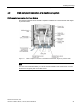
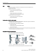
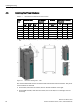
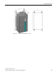
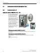
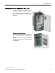
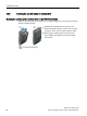
Table Of Contents
- PM230 Power Module, IP55
- Legal information - Warning notice system
- Table of contents
- 1 Changes in this manual
- 2 Fundamental safety instructions
- 3 Launch
- 4 Installing/mounting
- 5 Connecting
- 6 Service and maintenance
- 7 Technical data
- 7.1 Overload capability of the inverter
- 7.2 Cable cross-sections and tightening torques
- 7.3 Electromagnetic compatibility - Overview
- 7.4 Ambient conditions
- 7.5 General technical data
- 7.6 Specific technical data
- 7.7 Restrictions for special ambient conditions
- 7.8 Current reduction depending on pulse frequency
- 7.9 Electromagnetic compatibility of variable-speed drives
- 8 Spare parts and accessories
- A Appendix
- Index
Installing/mounting
4.3 Installing the Power Modules
PM230 Power Module, IP55
24 Hardware Installation Manual, 12/2016, A5E35319202B AB
4.3
Installing the Power Modules
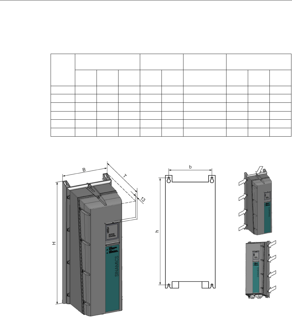
Table 4- 1 Dimensions and clearances to other devices
Frame
size
Dimensions (mm)
Drilling dimen-
sions (mm)
Mounting
Clearances to other de-
vices (mm)
Width
(W)
Height
(H)
Depth
1)
(D)
b
h
Screws/torque
(Nm)
Top
Bottom
Lateral
FSA
154
460
249
132
445
4 x M4 / 2.5
100
100
0
FSB
180
540
249
158
524
4 x M4 / 2.5
100
100
0
FSC 230 620 249 208 604 4 x M5 / 3 125 125 0
FSD
320
640
329
285
600
4 x M8 / 13
300
300
50
FSE 320 751 329 285 710 4 x M8 / 13 300 300 50
FSF
410
915
416
370
870
4 x M8 / 13
350
350
50
1) With an IOP, the depth increases by 17 mm; with the BOP
-2, or a dummy cover, it increases by 7
mm.
Figure 4-3 Dimension drawing FSA ... FSC
The screws marked with arrows connect the heat sink with the inverter enclosure. They must
not be loosened or removed!
● For the FSA, this means six screws, three on the left and three on the right.
● For the FSB and FSC, there are nine screws; four on the left, four on the right, and one
on the top.