
Installation Instructions
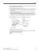
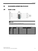
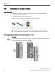
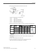

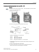
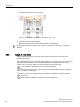
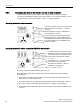
Table Of Contents
- PM230 Power Module, IP55
- Legal information - Warning notice system
- Table of contents
- 1 Changes in this manual
- 2 Fundamental safety instructions
- 3 Launch
- 4 Installing/mounting
- 5 Connecting
- 6 Service and maintenance
- 7 Technical data
- 7.1 Overload capability of the inverter
- 7.2 Cable cross-sections and tightening torques
- 7.3 Electromagnetic compatibility - Overview
- 7.4 Ambient conditions
- 7.5 General technical data
- 7.6 Specific technical data
- 7.7 Restrictions for special ambient conditions
- 7.8 Current reduction depending on pulse frequency
- 7.9 Electromagnetic compatibility of variable-speed drives
- 8 Spare parts and accessories
- A Appendix
- Index
Connecting
5.3 Connecting the line and motor cable at the inverter
PM230 Power Module, IP55
Hardware Installation Manual, 12/2016, A5E35319202B AB
37
Connecting the mains supply and motor, frame sizes FSD … FSF
Procedure
To connect the mains supply and motor to FSD … FSF Power Modules, proceed as follows:
1. Open the door of the Power Module.
2. Remove the terminal cover.
3. Remove the cable gland plate from the bottom of the inverter.
Diameters of the drill holes in the cable gland plates:
20.5 mm
Control cables
40.5 mm
Mains and motor cables, FSD
50.5 mm
Mains and motor cables, FSE
63.5 mm
Mains and motor cables, FSF
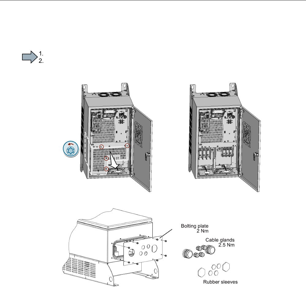
Figure 5-6 Bolting plates for PM230 FSD … FSF Power Modules
4. Assemble the cable glands with the prepared cables and EMC cable glands for the
control cables.
5. Seal any unused bushings with a rubber sleeve.
6. Secure the bolting plate to the inverter enclosure. Tightening torque 2 Nm.
Make sure that the seal of the bolting plate is not damaged.