
Operating Instructions

Communication via PROFIBUS and PROFINET
3.6 Communication via PROFINET
Fieldbuses
62 Function Manual, 04/2018, FW V4.7 SP10, A5E34229197B AE
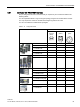
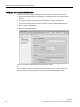
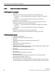
Table 3- 14 Connector pin assignments
Signal X150 P1/
X150 P2
(RJ45)
X03/X04
(RJ45)
X03/X04
(M12)
TX-, transmit data -
1
1
1
RX+, receive data +
3
2
2
TX+ Transmit data +
2
3
3
RX-, receive data -
6
6
4
---
4
4
---
---
5
5
---
--- 7 7 ---
---
8
8
---
Recommended connector
RJ45, IP20: 6GK1901-1BB10-2Ax0
Information for assembling the SIMATIC NET Industrial Ethernet FastConnect RF45 plug
180 can be found on the Internet:
Assembly instructions for the SIMATIC NET Industrial Ethernet FastConnect RJ45 plug
(http://support.automation.siemens.com/WW/view/en/37217116/133300)
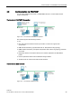
3.6.2
Integrating inverters into PROFINET
To connect the inverter to a control via PROFINET, proceed as follows:
Procedure
1. Integrate the inverter in the bus system (e.g. ring topology) of the control using
PROFINET cables and the two PROFINET sockets X150-P1 and X150-P2 or X03 and
X04.
The position of the sockets is available in the operating instructions for the inverter.
Pin assignment:
Converter with PROFINET interface (Page 61).
The maximum permitted cable length from the previous station and to the subsequent
one is 100 m.
2. Externally supply the inverter with 24 V DC through terminals 31 and 32 or via X01.
The external 24 V supply is only required if communications with the control system
should also operate when the line voltage is switched off.
You have now connected the inverter to the control system via PROFINET
❒