
Operating Instructions

Signals and monitoring functions
Function diagrams
2-637
© Siemens AG 2008 - 2013 All Rights Reserved
SINAMICS G120 CU230P-2 Control Units List Manual (LH9), 01/2013
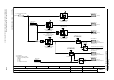
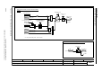
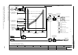
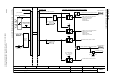
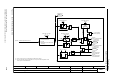
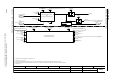
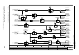
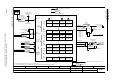
Fig. 2-127 8020 – Monitoring functions 1
- 8020 -
Function diagram
87654321
fp_8020_97_01.vsd
Signals and monitoring functions
G120 CU230P-2
12.12.2012 V4.6
Monitoring functions 1
T0
0
1
[8010.2]
+
–
[3050.8]
1
0
T0
1
1
0
[6730.1]
1
0
[6714.8]
0
1
0T
0T
0T
[6730.4]
0
1
0
T0
1
0
0
0
1
n_min
p1080
ZSW monitor 1
r2197
r2197
.0
n_hysteresis 3
p2150
r2169
n_act smth message [1/min]
r1119
RFG setp at inp [1/min]
r0063
n_act [1/min]
r0070
Vdc act val [V]
r0068
I_act abs val [Aeff]
r0072
U_output [Veff]
n_hysteresis 3
p2150
n_standst n_thresh
p1226
Pulse suppr t_del
p1228
Vdc thresh val
p2172
t_del Vdc
p2173
t_del Vdc
p2173
t_del I_thresh rch
p2171
I_thres
p2170
I_thres
p2170
t_del I_thresh rch
p2171
No load t_delay
p2180
ZSW 2
r0053
r0053
.2
[2511.6]
ZSW monitor 1
r2197
r2197
.4
ZSW 2
r0053
r0053
.6
[2511.6]
ZSW monitor 1
r2197
r2197
.5
ZSW 2
r0053
r0053
.1
[2511.6]
ZSW monitor 1
r2197
r2197
.9
ZSW 2
r0053
r0053
.7
[2511.6]
ZSW monitor 1
r2197
r2197
.10
ZSW 2
r0053
r0053
.8
[2511.6]
ZSW monitor 1
r2197
r2197
.8
ZSW 2
r0053
r0053
.3
[2511.6]
ZSW monitor 2
r2198
r2198
.8
ZSW monitor 1
r2197
r2197
.11
Enable Pulses
|n_act| <= p1080
|n_act| >= n_set
|n_act| <= n_standst
Vdc_act <= p2172
Vdc_act > p2172
I_act >= p2170
I_act < p2170
Output load present
Drive: No motor detected
A07929
-1
1
0
[0]
1
M_act_filt T
0 ... 1000000 [ms]
p3233 [D] (100)
1
0