
Operating Instructions
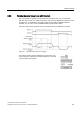

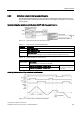
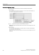
Table Of Contents
- Converter with CU230P-2 Control Units
- Legal information
- Changes in this manual
- Table of contents
- 1 Fundamental safety instructions
- 2 Introduction
- 3 Description
- 4 Installing
- 4.1 Overview of the inverter installation
- 4.2 Installing reactors, filters and braking resistors
- 4.3 Installing Power Module
- 4.4 Installing Control Unit
- 4.5 Connecting inverters in compliance with EMC
- 5 Commissioning
- 6 Adapting the terminal strip
- 7 Configuring the fieldbus
- 8 Setting functions
- 8.1 Overview of the inverter functions
- 8.2 Inverter control
- 8.2.1 Switching the motor on and off
- 8.2.2 Inverter control using digital inputs
- 8.2.3 Two-wire control: method 1
- 8.2.4 Two-wire control, method 2
- 8.2.5 Two-wire control, method 3
- 8.2.6 Three-wire control, method 1
- 8.2.7 Three-wire control, method 2
- 8.2.8 Running the motor in jog mode (JOG function)
- 8.2.9 Switching over the inverter control (command data set)
- 8.3 Setpoints
- 8.4 Setpoint calculation
- 8.5 Motor control
- 8.6 Protection and monitoring functions
- 8.7 Application-specific functions
- 8.7.1 Unit changeover
- 8.7.2 Calculating the energy saving
- 8.7.3 Electrically braking the motor
- 8.7.4 Flying restart – switching on while the motor is running
- 8.7.5 Automatic switch-on
- 8.7.6 Kinetic buffering (Vdc min control)
- 8.7.7 PID technology controller
- 8.7.8 Free technology controllers
- 8.7.9 Monitoring the load torque (system protection)
- 8.7.10 Load failure monitoring
- 8.7.11 Real time clock (RTC)
- 8.7.12 Time switch (DTC)
- 8.7.13 Record temperature via temperature-dependent resistances
- 8.7.14 Essential service mode
- 8.7.15 Multi-zone control
- 8.7.16 Bypass
- 8.7.17 Cascade control and hibernation mode
- 8.7.18 Free function blocks
- 8.8 Switchover between different settings
- 9 Backing up data and series commissioning
- 10 Corrective maintenance
- 10.1 Overview of replacing converter components
- 10.2 Replace Control Unit
- 10.3 Replacing the Control Unit without data backup
- 10.4 Replacing a Control Unit with active know-how protection
- 10.5 Replacing a Power Module
- 10.6 Upgrading the firmware
- 10.7 Firmware downgrade
- 10.8 Correcting an unsuccessful firmware upgrade or downgrade
- 10.9 If the converter no longer responds
- 11 Alarms, faults and system messages
- 12 Technical data
- A Appendix
- Index

Setting functions
8.3 Setpoints
Converter with CU230P-2 Control Units
Operating Instructions, 04/2014, FW V4.7, A5E34257946B AA
155
8.3
Setpoints
The inverter receives its main setpoint from the setpoint source. The main setpoint generally
specifies the motor speed.
Figure 8-11 Setpoint sources for the inverter
You have the following options when selecting the source of the main setpoint:
● Inverter analog input.
● Inverter fieldbus interface.
● Motorized potentiometer simulated in the inverter.
● Fixed setpoints saved in the inverter.
You have the same selection options when selecting the source of the supplementary
setpoint.
Under the following conditions, the inverter switches from the main setpoint to other
setpoints:
● When the technology controller is active and appropriately interconnected, its output
specifies the motor speed.
● When jogging is active.
● When controlling from an operator panel or the STARTER PC tool.