
Operating Instructions
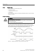

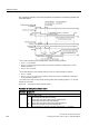
Table Of Contents
- Converter with CU230P-2 Control Units
- Legal information
- Changes in this manual
- Table of contents
- 1 Fundamental safety instructions
- 2 Introduction
- 3 Description
- 4 Installing
- 4.1 Overview of the inverter installation
- 4.2 Installing reactors, filters and braking resistors
- 4.3 Installing Power Module
- 4.4 Installing Control Unit
- 4.5 Connecting inverters in compliance with EMC
- 5 Commissioning
- 6 Adapting the terminal strip
- 7 Configuring the fieldbus
- 8 Setting functions
- 8.1 Overview of the inverter functions
- 8.2 Inverter control
- 8.2.1 Switching the motor on and off
- 8.2.2 Inverter control using digital inputs
- 8.2.3 Two-wire control: method 1
- 8.2.4 Two-wire control, method 2
- 8.2.5 Two-wire control, method 3
- 8.2.6 Three-wire control, method 1
- 8.2.7 Three-wire control, method 2
- 8.2.8 Running the motor in jog mode (JOG function)
- 8.2.9 Switching over the inverter control (command data set)
- 8.3 Setpoints
- 8.4 Setpoint calculation
- 8.5 Motor control
- 8.6 Protection and monitoring functions
- 8.7 Application-specific functions
- 8.7.1 Unit changeover
- 8.7.2 Calculating the energy saving
- 8.7.3 Electrically braking the motor
- 8.7.4 Flying restart – switching on while the motor is running
- 8.7.5 Automatic switch-on
- 8.7.6 Kinetic buffering (Vdc min control)
- 8.7.7 PID technology controller
- 8.7.8 Free technology controllers
- 8.7.9 Monitoring the load torque (system protection)
- 8.7.10 Load failure monitoring
- 8.7.11 Real time clock (RTC)
- 8.7.12 Time switch (DTC)
- 8.7.13 Record temperature via temperature-dependent resistances
- 8.7.14 Essential service mode
- 8.7.15 Multi-zone control
- 8.7.16 Bypass
- 8.7.17 Cascade control and hibernation mode
- 8.7.18 Free function blocks
- 8.8 Switchover between different settings
- 9 Backing up data and series commissioning
- 10 Corrective maintenance
- 10.1 Overview of replacing converter components
- 10.2 Replace Control Unit
- 10.3 Replacing the Control Unit without data backup
- 10.4 Replacing a Control Unit with active know-how protection
- 10.5 Replacing a Power Module
- 10.6 Upgrading the firmware
- 10.7 Firmware downgrade
- 10.8 Correcting an unsuccessful firmware upgrade or downgrade
- 10.9 If the converter no longer responds
- 11 Alarms, faults and system messages
- 12 Technical data
- A Appendix
- Index

Setting functions
8.7 Application-specific functions
Converter with CU230P-2 Control Units
208 Operating Instructions, 04/2014, FW V4.7, A5E34257946B AA
The principle of operation of the other parameters is explained in the following diagram and
in the table below.
1)
The inverter automatically acknowledges faults under the following conditions:
• p1210 = 1 or 26: Always.
• p1210 = 4 or 6: If the command to switch-on the motor is available at a digital input or via the
fieldbus (ON/OFF1 = 1).
• p1210 = 14 or 16: Never.
2)
The inverter attempts to automatically switch the motor on under the following conditions:
• p1210 = 1: Never.
• p1210 = 4, 6, 14, 16, or 26: If the command to switch-on the motor is available at a digital input
or via the fieldbus (ON/OFF1 = 1).
3)
If no fault has occurred one second after the flying restart and magnetizing (r0056.4 = 1), the start
attempt was successful.
Figure 8-26 Time response of the automatic restart
Parameter for setting the automatic restart
Parameter
Explanation
p1210
Automatic restart mode (factory setting: 0)
0:
1:
4:
6:
14:
16:
26:
Disable automatic restart.
Acknowledge all faults without restarting.
Restart after power failure without further restart attempts.
Restart after fault with further restart attempts.
Restart after power failure after manual acknowledgement.
Restart after fault after manual acknowledgement.
Acknowledgement of all faults and restart with ON/OFF1 = 1 command.