
Operating Instructions
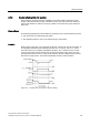

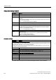
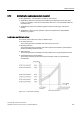
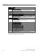

Table Of Contents
- Converter with CU230P-2 Control Units
- Legal information
- Changes in this manual
- Table of contents
- 1 Fundamental safety instructions
- 2 Introduction
- 3 Description
- 4 Installing
- 4.1 Overview of the inverter installation
- 4.2 Installing reactors, filters and braking resistors
- 4.3 Installing Power Module
- 4.4 Installing Control Unit
- 4.5 Connecting inverters in compliance with EMC
- 5 Commissioning
- 6 Adapting the terminal strip
- 7 Configuring the fieldbus
- 8 Setting functions
- 8.1 Overview of the inverter functions
- 8.2 Inverter control
- 8.2.1 Switching the motor on and off
- 8.2.2 Inverter control using digital inputs
- 8.2.3 Two-wire control: method 1
- 8.2.4 Two-wire control, method 2
- 8.2.5 Two-wire control, method 3
- 8.2.6 Three-wire control, method 1
- 8.2.7 Three-wire control, method 2
- 8.2.8 Running the motor in jog mode (JOG function)
- 8.2.9 Switching over the inverter control (command data set)
- 8.3 Setpoints
- 8.4 Setpoint calculation
- 8.5 Motor control
- 8.6 Protection and monitoring functions
- 8.7 Application-specific functions
- 8.7.1 Unit changeover
- 8.7.2 Calculating the energy saving
- 8.7.3 Electrically braking the motor
- 8.7.4 Flying restart – switching on while the motor is running
- 8.7.5 Automatic switch-on
- 8.7.6 Kinetic buffering (Vdc min control)
- 8.7.7 PID technology controller
- 8.7.8 Free technology controllers
- 8.7.9 Monitoring the load torque (system protection)
- 8.7.10 Load failure monitoring
- 8.7.11 Real time clock (RTC)
- 8.7.12 Time switch (DTC)
- 8.7.13 Record temperature via temperature-dependent resistances
- 8.7.14 Essential service mode
- 8.7.15 Multi-zone control
- 8.7.16 Bypass
- 8.7.17 Cascade control and hibernation mode
- 8.7.18 Free function blocks
- 8.8 Switchover between different settings
- 9 Backing up data and series commissioning
- 10 Corrective maintenance
- 10.1 Overview of replacing converter components
- 10.2 Replace Control Unit
- 10.3 Replacing the Control Unit without data backup
- 10.4 Replacing a Control Unit with active know-how protection
- 10.5 Replacing a Power Module
- 10.6 Upgrading the firmware
- 10.7 Firmware downgrade
- 10.8 Correcting an unsuccessful firmware upgrade or downgrade
- 10.9 If the converter no longer responds
- 11 Alarms, faults and system messages
- 12 Technical data
- A Appendix
- Index

Setting functions
8.7 Application-specific functions
Converter with CU230P-2 Control Units
220 Operating Instructions, 04/2014, FW V4.7, A5E34257946B AA
8.7.11
Real time clock (RTC)
The real time clock is the basis for time-dependent process controls, e.g.:
● To reduce the temperature of a heating control during the night
● Increase the pressure of a water supply at certain times during the day
Real time clock: Format and commissioning
The real time clock starts as soon as the Control Unit power supply is switched on for the
first time. The real time clock comprises the time in a 24 hour format and the date in the
"day, month, year" format.
After a Control Unit power supply interruption, the real time clock continues to run for approx.
five days.
If you wish to use the real time clock, you must set the time and date once when
commissioning. If you restore the inverter factory setting, the real time clock parameters are
not reset.
Parameter
Real time clock (RTC)
p8400[0]
RTC time, hour (0 … 23)
p8400[1]
RTC time, minute (0 … 59)
p8400[2]
RTC time, second (0 … 59)
p8401[0]
RTC date, day (1 … 31)
p8401[1]
RTC date, month (1 … 12)
p8401[2]
RTC date, year (1 … 9999)
r8404
RTC weekday
1: Monday
2: Tuesday
3: Wednesday
4: Thursday
5: Friday
6: Saturday
7: Sunday
p8405
RTC activate/deactivate alarm A01098
Sets whether the real time clock issues an alarm if the time is not running in
synchronism (e.g. after a longer power supply interruption).
0: Alarm A01098 deactivated
1: Alarm A01098 activated