
Operating Instructions


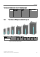

Table Of Contents
- Converter with CU230P-2 Control Units
- Legal information
- Changes in this manual
- Table of contents
- 1 Fundamental safety instructions
- 2 Introduction
- 3 Description
- 4 Installing
- 4.1 Overview of the inverter installation
- 4.2 Installing reactors, filters and braking resistors
- 4.3 Installing Power Module
- 4.4 Installing Control Unit
- 4.5 Connecting inverters in compliance with EMC
- 5 Commissioning
- 6 Adapting the terminal strip
- 7 Configuring the fieldbus
- 8 Setting functions
- 8.1 Overview of the inverter functions
- 8.2 Inverter control
- 8.2.1 Switching the motor on and off
- 8.2.2 Inverter control using digital inputs
- 8.2.3 Two-wire control: method 1
- 8.2.4 Two-wire control, method 2
- 8.2.5 Two-wire control, method 3
- 8.2.6 Three-wire control, method 1
- 8.2.7 Three-wire control, method 2
- 8.2.8 Running the motor in jog mode (JOG function)
- 8.2.9 Switching over the inverter control (command data set)
- 8.3 Setpoints
- 8.4 Setpoint calculation
- 8.5 Motor control
- 8.6 Protection and monitoring functions
- 8.7 Application-specific functions
- 8.7.1 Unit changeover
- 8.7.2 Calculating the energy saving
- 8.7.3 Electrically braking the motor
- 8.7.4 Flying restart – switching on while the motor is running
- 8.7.5 Automatic switch-on
- 8.7.6 Kinetic buffering (Vdc min control)
- 8.7.7 PID technology controller
- 8.7.8 Free technology controllers
- 8.7.9 Monitoring the load torque (system protection)
- 8.7.10 Load failure monitoring
- 8.7.11 Real time clock (RTC)
- 8.7.12 Time switch (DTC)
- 8.7.13 Record temperature via temperature-dependent resistances
- 8.7.14 Essential service mode
- 8.7.15 Multi-zone control
- 8.7.16 Bypass
- 8.7.17 Cascade control and hibernation mode
- 8.7.18 Free function blocks
- 8.8 Switchover between different settings
- 9 Backing up data and series commissioning
- 10 Corrective maintenance
- 10.1 Overview of replacing converter components
- 10.2 Replace Control Unit
- 10.3 Replacing the Control Unit without data backup
- 10.4 Replacing a Control Unit with active know-how protection
- 10.5 Replacing a Power Module
- 10.6 Upgrading the firmware
- 10.7 Firmware downgrade
- 10.8 Correcting an unsuccessful firmware upgrade or downgrade
- 10.9 If the converter no longer responds
- 11 Alarms, faults and system messages
- 12 Technical data
- A Appendix
- Index

Description
3.3 Power Module
Converter with CU230P-2 Control Units
Operating Instructions, 04/2014, FW V4.7, A5E34257946B AA
27
PM230, 3 AC 400 V - Pump and fan applications
The PM230 Power Module is available without a filter or with integrated class A line filter.
Range of order numbers:
Range of order numbers:
•
IP20:
•
Push through:
6SL3210
-1NE…
6SL3211
-1NE…
Frame size
FSA
FSB
FSC
FSD
FSE
FSF
Power range (kW), IP20
0,37 … 3
4 … 7,5
11 … 18,5
22 … 37
45 … 55
75 … 90
Power range (kW), PT
3
7,5
18,5
---
---
---
PM330, 3 AC 400 V - Pump, fan and compressor applications
The PM330 Power Module is available as an unfiltered device with IP20 degree of
protection. External line filters are available as an option, see Section
Range of order numbers: 6SL3310-1PE…
Frame size
GX
Power range (kW)
160 … 200
PM240, 3 AC 400 V - Standard areas of application
The PM240 Power Module is available without a filter or with an integrated class A line filter
with degree of protection IP20. The PM240 allows dynamic braking via an external braking
resistor.
Order number range: 6SL3224-0BE… and 6SL3224-0XE…
Frame size
FSA
FSB
FSC
FSD
FSE
FSF
FSGX
Power range (kW)
0.37 … 1.5
2.2 … 4
7.5 … 15
18.5 … 30
37 … 45
55 … 132
160 … 250
PM240-2, 3 AC 400 V - standard areas of application
The PM240-2 Power Module is available without a filter or with an integrated class A line
filter. The PM240-2 permits dynamic braking via an external braking resistor.
Range of order numbers:
•
IP20:
•
Push through:
6SL3210
-1PE…
6SL3211
-1PE…
Frame size
FSA
FSB
FSC
Power range (kW), IP20
0,55 … 3,0
4,0 … 7,5
11 … 15
Power range (kW), PT
3,0
7,5
15