
Operating Instructions
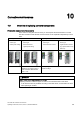

Table Of Contents
- Converter with CU230P-2 Control Units
- Legal information
- Changes in this manual
- Table of contents
- 1 Fundamental safety instructions
- 2 Introduction
- 3 Description
- 4 Installing
- 4.1 Overview of the inverter installation
- 4.2 Installing reactors, filters and braking resistors
- 4.3 Installing Power Module
- 4.4 Installing Control Unit
- 4.5 Connecting inverters in compliance with EMC
- 5 Commissioning
- 6 Adapting the terminal strip
- 7 Configuring the fieldbus
- 8 Setting functions
- 8.1 Overview of the inverter functions
- 8.2 Inverter control
- 8.2.1 Switching the motor on and off
- 8.2.2 Inverter control using digital inputs
- 8.2.3 Two-wire control: method 1
- 8.2.4 Two-wire control, method 2
- 8.2.5 Two-wire control, method 3
- 8.2.6 Three-wire control, method 1
- 8.2.7 Three-wire control, method 2
- 8.2.8 Running the motor in jog mode (JOG function)
- 8.2.9 Switching over the inverter control (command data set)
- 8.3 Setpoints
- 8.4 Setpoint calculation
- 8.5 Motor control
- 8.6 Protection and monitoring functions
- 8.7 Application-specific functions
- 8.7.1 Unit changeover
- 8.7.2 Calculating the energy saving
- 8.7.3 Electrically braking the motor
- 8.7.4 Flying restart – switching on while the motor is running
- 8.7.5 Automatic switch-on
- 8.7.6 Kinetic buffering (Vdc min control)
- 8.7.7 PID technology controller
- 8.7.8 Free technology controllers
- 8.7.9 Monitoring the load torque (system protection)
- 8.7.10 Load failure monitoring
- 8.7.11 Real time clock (RTC)
- 8.7.12 Time switch (DTC)
- 8.7.13 Record temperature via temperature-dependent resistances
- 8.7.14 Essential service mode
- 8.7.15 Multi-zone control
- 8.7.16 Bypass
- 8.7.17 Cascade control and hibernation mode
- 8.7.18 Free function blocks
- 8.8 Switchover between different settings
- 9 Backing up data and series commissioning
- 10 Corrective maintenance
- 10.1 Overview of replacing converter components
- 10.2 Replace Control Unit
- 10.3 Replacing the Control Unit without data backup
- 10.4 Replacing a Control Unit with active know-how protection
- 10.5 Replacing a Power Module
- 10.6 Upgrading the firmware
- 10.7 Firmware downgrade
- 10.8 Correcting an unsuccessful firmware upgrade or downgrade
- 10.9 If the converter no longer responds
- 11 Alarms, faults and system messages
- 12 Technical data
- A Appendix
- Index

Corrective maintenance
10.4 Replacing a Control Unit with active know-how protection
Converter with CU230P-2 Control Units
276 Operating Instructions, 04/2014, FW V4.7, A5E34257946B AA
10.4
Replacing a Control Unit with active know-how protection
Replacing devices during know-how protection without copy protection
For know-how protection without copy protection, the converter settings can be transferred to
another converter using a memory card.
See also:
● Saving setting on memory card (Page 253)
● Transferring the setting from the memory card (Page 256)
Replacing devices for know-how protection with copy protection
The know-how protection with copy protection prevents the inverter settings from being
copied and passed on. This function is predominantly used by machine manufacturers.
If know-how protection with copy protection is active, the inverter cannot be replaced as
described in "Replace Control Unit (Page 273)".
However, to allow the inverter to be replaced, you must use a Siemens memory card, and
the machine manufacturer must have an identical machine that he uses as sample.
There are two options for replacing the device:
Option 1: The machine manufacturer only knows the serial number of the new inverter
● The end customer provides the machine manufacturer with the following information:
– For which machine must the inverter be replaced?
– What is the serial number (r7758) of the new inverter?
● The machine manufacturer goes online on the sample machine.
– deactivates the know-how protection, see Settings for the know-how protection
(Page 268)
– enters the serial number of the new inverter in p7759
– enters the serial number of the inserted memory card as reference serial number in
p7769
– activates the know-how protection with copy protection ("Copy RAM to ROM" must be
activated!), see Settings for the know-how protection (Page 268)
– writes the configuration with p0971 = 1 to the memory card
– sends the memory card to the end customer
● The end customer inserts the memory card and switches on the inverter.
When powering up, the inverter checks the serial numbers of the card and when there is a
match, the inverter goes into the "ready to start" state.
If the numbers do not match, then the inverter signals fault F13100 (no valid memory card).