
Operating Instructions

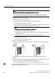
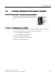

Table Of Contents
- Converter with CU230P-2 Control Units
- Legal information
- Changes in this manual
- Table of contents
- 1 Fundamental safety instructions
- 2 Introduction
- 3 Description
- 4 Installing
- 4.1 Overview of the inverter installation
- 4.2 Installing reactors, filters and braking resistors
- 4.3 Installing Power Module
- 4.4 Installing Control Unit
- 4.5 Connecting inverters in compliance with EMC
- 5 Commissioning
- 6 Adapting the terminal strip
- 7 Configuring the fieldbus
- 8 Setting functions
- 8.1 Overview of the inverter functions
- 8.2 Inverter control
- 8.2.1 Switching the motor on and off
- 8.2.2 Inverter control using digital inputs
- 8.2.3 Two-wire control: method 1
- 8.2.4 Two-wire control, method 2
- 8.2.5 Two-wire control, method 3
- 8.2.6 Three-wire control, method 1
- 8.2.7 Three-wire control, method 2
- 8.2.8 Running the motor in jog mode (JOG function)
- 8.2.9 Switching over the inverter control (command data set)
- 8.3 Setpoints
- 8.4 Setpoint calculation
- 8.5 Motor control
- 8.6 Protection and monitoring functions
- 8.7 Application-specific functions
- 8.7.1 Unit changeover
- 8.7.2 Calculating the energy saving
- 8.7.3 Electrically braking the motor
- 8.7.4 Flying restart – switching on while the motor is running
- 8.7.5 Automatic switch-on
- 8.7.6 Kinetic buffering (Vdc min control)
- 8.7.7 PID technology controller
- 8.7.8 Free technology controllers
- 8.7.9 Monitoring the load torque (system protection)
- 8.7.10 Load failure monitoring
- 8.7.11 Real time clock (RTC)
- 8.7.12 Time switch (DTC)
- 8.7.13 Record temperature via temperature-dependent resistances
- 8.7.14 Essential service mode
- 8.7.15 Multi-zone control
- 8.7.16 Bypass
- 8.7.17 Cascade control and hibernation mode
- 8.7.18 Free function blocks
- 8.8 Switchover between different settings
- 9 Backing up data and series commissioning
- 10 Corrective maintenance
- 10.1 Overview of replacing converter components
- 10.2 Replace Control Unit
- 10.3 Replacing the Control Unit without data backup
- 10.4 Replacing a Control Unit with active know-how protection
- 10.5 Replacing a Power Module
- 10.6 Upgrading the firmware
- 10.7 Firmware downgrade
- 10.8 Correcting an unsuccessful firmware upgrade or downgrade
- 10.9 If the converter no longer responds
- 11 Alarms, faults and system messages
- 12 Technical data
- A Appendix
- Index

Corrective maintenance
10.7 Firmware downgrade
Converter with CU230P-2 Control Units
Operating Instructions, 04/2014, FW V4.7, A5E34257946B AA
281
10.7
Firmware downgrade
When downgrading the firmware, you replace the inverter firmware by an older version. Only
downgrade the firmware to an older version if, after replacing an inverter, you require the
same firmware in all of your inverters.
Precondition
● The firmware version of your inverter is at least V4.6.
● You have the memory card with the firmware that matches the inverter.
● Inverter and memory card have different firmware versions.
● You have backed up your settings on the memory card, in an operator panel or in a PC.
Procedure
Proceed as follows to downgrade the inverter firmware to an older version:
1. Switch off the inverter power supply.
2. Wait until all LEDs on the inverter go dark.
3. Insert the card with the matching firmware into the inverter slot until it latches into place.
4. Switch on the inverter power supply.
5. The inverter transfers the firmware from the memory card into its memory.
The transfer takes approximately 5 … 10 minutes.
While data is being transferred, the LED RDY on the inverter stays red. The LED BF
flashes orange with a variable frequency.
6. At the end of the transfer, the LED RDY and BF slowly flash red (0.5 Hz).