
Operating Instructions
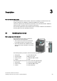


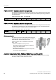
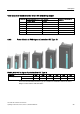

Table Of Contents
- Converter with CU230P-2 Control Units
- Legal information
- Changes in this manual
- Table of contents
- 1 Fundamental safety instructions
- 2 Introduction
- 3 Description
- 4 Installing
- 4.1 Overview of the inverter installation
- 4.2 Installing reactors, filters and braking resistors
- 4.3 Installing Power Module
- 4.4 Installing Control Unit
- 4.5 Connecting inverters in compliance with EMC
- 5 Commissioning
- 6 Adapting the terminal strip
- 7 Configuring the fieldbus
- 8 Setting functions
- 8.1 Overview of the inverter functions
- 8.2 Inverter control
- 8.2.1 Switching the motor on and off
- 8.2.2 Inverter control using digital inputs
- 8.2.3 Two-wire control: method 1
- 8.2.4 Two-wire control, method 2
- 8.2.5 Two-wire control, method 3
- 8.2.6 Three-wire control, method 1
- 8.2.7 Three-wire control, method 2
- 8.2.8 Running the motor in jog mode (JOG function)
- 8.2.9 Switching over the inverter control (command data set)
- 8.3 Setpoints
- 8.4 Setpoint calculation
- 8.5 Motor control
- 8.6 Protection and monitoring functions
- 8.7 Application-specific functions
- 8.7.1 Unit changeover
- 8.7.2 Calculating the energy saving
- 8.7.3 Electrically braking the motor
- 8.7.4 Flying restart – switching on while the motor is running
- 8.7.5 Automatic switch-on
- 8.7.6 Kinetic buffering (Vdc min control)
- 8.7.7 PID technology controller
- 8.7.8 Free technology controllers
- 8.7.9 Monitoring the load torque (system protection)
- 8.7.10 Load failure monitoring
- 8.7.11 Real time clock (RTC)
- 8.7.12 Time switch (DTC)
- 8.7.13 Record temperature via temperature-dependent resistances
- 8.7.14 Essential service mode
- 8.7.15 Multi-zone control
- 8.7.16 Bypass
- 8.7.17 Cascade control and hibernation mode
- 8.7.18 Free function blocks
- 8.8 Switchover between different settings
- 9 Backing up data and series commissioning
- 10 Corrective maintenance
- 10.1 Overview of replacing converter components
- 10.2 Replace Control Unit
- 10.3 Replacing the Control Unit without data backup
- 10.4 Replacing a Control Unit with active know-how protection
- 10.5 Replacing a Power Module
- 10.6 Upgrading the firmware
- 10.7 Firmware downgrade
- 10.8 Correcting an unsuccessful firmware upgrade or downgrade
- 10.9 If the converter no longer responds
- 11 Alarms, faults and system messages
- 12 Technical data
- A Appendix
- Index

Description
3.4 Components for the Power Modules
Converter with CU230P-2 Control Units
30 Operating Instructions, 04/2014, FW V4.7, A5E34257946B AA
3.4
Components for the Power Modules
3.4.1
Line filter
With a line filter, the inverter can achieve
a higher radio interference class. An
external filter is not required for
inverters
with integrated line filter.
Adjacent examples of line filters.
Filters comply with Class A, or B
according to EN55011: 2009.
for PM240
FSA
for PM240 FSGX
External line filters for PM240
Power Module 6SL3224-…
Power
Line filter, class A
FSA …0BE13-7UA0, …0BE15-5UA0,
…0BE17-5UA0, …0BE21-1UA0,
…0BE21-5UA0
0.37 kW … 1.5 kW 6SE6400-2FA00-6AD0
FSF
…0BE38-8UA0, …0BE41-1UA0
110 kW … 132 kW
6SL3203-0BE32-5AA0
FSGX
…0XE41-3UA0, …0XE41-6UA0
160 kW … 200 kW
6SL3000-0BE34-4AA0
…0XE42-0UA0
250 kW
6SL3000-0BE36-0AA0
Power Module 6SL3224-…
Power
Line filter, class B
FSA …0BE13-7UA0, …0BE15-5UA0,
…0BE17-5UA0, …0BE21-1UA0,
…0BE21-5UA0
0.37 kW … 1.5 kW 6SE6400-2FB00-6AD0
FSB …0BE22-2AA0, …0BE23-0AA0,
…0BE24-0AA0
2.2 kW … 4.0 kW 6SL3203-0BE21-6SA0
FSC …0BE25-5UA0, …0BE27-5UA0,
…0BE31-1UA0
7.5 kW … 15.0 kW 6SL3203-0BD23-8SA0
External line filters for PM250
Power Module 6SL3225-…
Power
Line filter, class B
FSC …0BE25-5AA0, …0BE27-5AA0,
…0BE31-1AA0
7.5 kW … 15.0 kW 6SL3203-0BD23-8SA0
External line filters for PM330
Power Module 6SL3310-…
Power
Line filter, class A
GX …1PE33-0AA0, …1PE33-7AA0 160 kW … 200 kW 6SL3000-0BE33-1AA0