
Operating Instructions
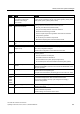
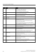
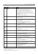
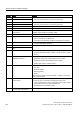
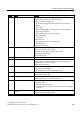
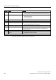
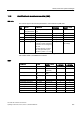
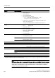
Table Of Contents
- Converter with CU230P-2 Control Units
- Legal information
- Changes in this manual
- Table of contents
- 1 Fundamental safety instructions
- 2 Introduction
- 3 Description
- 4 Installing
- 4.1 Overview of the inverter installation
- 4.2 Installing reactors, filters and braking resistors
- 4.3 Installing Power Module
- 4.4 Installing Control Unit
- 4.5 Connecting inverters in compliance with EMC
- 5 Commissioning
- 6 Adapting the terminal strip
- 7 Configuring the fieldbus
- 8 Setting functions
- 8.1 Overview of the inverter functions
- 8.2 Inverter control
- 8.2.1 Switching the motor on and off
- 8.2.2 Inverter control using digital inputs
- 8.2.3 Two-wire control: method 1
- 8.2.4 Two-wire control, method 2
- 8.2.5 Two-wire control, method 3
- 8.2.6 Three-wire control, method 1
- 8.2.7 Three-wire control, method 2
- 8.2.8 Running the motor in jog mode (JOG function)
- 8.2.9 Switching over the inverter control (command data set)
- 8.3 Setpoints
- 8.4 Setpoint calculation
- 8.5 Motor control
- 8.6 Protection and monitoring functions
- 8.7 Application-specific functions
- 8.7.1 Unit changeover
- 8.7.2 Calculating the energy saving
- 8.7.3 Electrically braking the motor
- 8.7.4 Flying restart – switching on while the motor is running
- 8.7.5 Automatic switch-on
- 8.7.6 Kinetic buffering (Vdc min control)
- 8.7.7 PID technology controller
- 8.7.8 Free technology controllers
- 8.7.9 Monitoring the load torque (system protection)
- 8.7.10 Load failure monitoring
- 8.7.11 Real time clock (RTC)
- 8.7.12 Time switch (DTC)
- 8.7.13 Record temperature via temperature-dependent resistances
- 8.7.14 Essential service mode
- 8.7.15 Multi-zone control
- 8.7.16 Bypass
- 8.7.17 Cascade control and hibernation mode
- 8.7.18 Free function blocks
- 8.8 Switchover between different settings
- 9 Backing up data and series commissioning
- 10 Corrective maintenance
- 10.1 Overview of replacing converter components
- 10.2 Replace Control Unit
- 10.3 Replacing the Control Unit without data backup
- 10.4 Replacing a Control Unit with active know-how protection
- 10.5 Replacing a Power Module
- 10.6 Upgrading the firmware
- 10.7 Firmware downgrade
- 10.8 Correcting an unsuccessful firmware upgrade or downgrade
- 10.9 If the converter no longer responds
- 11 Alarms, faults and system messages
- 12 Technical data
- A Appendix
- Index

Alarms, faults and system messages
11.5 List of alarms and faults
Converter with CU230P-2 Control Units
Operating Instructions, 04/2014, FW V4.7, A5E34257946B AA
301
Number
Cause
Remedy
F01034 Switching over units: Calculation of
the parameter values after
reference value change
unsuccessful
Select the value of the reference parameter so that the parameters
involved can be calculated in the per unit notation (p0304, p0305, p0310,
p0596, p2000, p2001, p2002, p2003, r2004).
A01053
System overload measured
The maximum computing power of the control unit was exceeded. The
following measures reduce the load on the control unit:
• Use only one data record (CDS and DDS)
• Only use the safety features of the basic functions
• Deactivate the technology controller
• Use the simple ramp-function generator rather than the extended
ramp-function generator
• Do not use any free function components
• Reduce the sampling time of the free function blocks
F01054 System limit exceeded
F01122 Frequency at the probe input too
high
Reduce the frequency of the pulses at the probe input.
A01590
Motor maintenance interval lapsed
Carry out maintenance and reset the maintenance interval (p0651).
A01900 PROFIBUS: Configuration
telegram faulty
Explanation: A PROFIBUS master is attempting to establish a connection
with a faulty configuration telegram.
Check the bus configuration on the master and slave side.
A01910
F01910
Setpoint timeout The alarm is generated when p2040 ≠ 0 ms and one of the following
causes is present:
• The bus connection is interrupted
• The Modbus master is switched off
• Communications error (CRC, parity bit, logical error)
• An excessively low value for the fieldbus monitoring time (p2040)
A01920 PROFIBUS: Cyclic connection
interrupt
Explanation: The cyclic connection to PROFIBUS master is interrupted.
Establish the PROFIBUS connection and activate the PROFIBUS master
with cyclic operation.
F03505 Analog input, wire break Check the wiring for interruptions.
Check the level of the injected signal.
The input current measured by the analog input can be read out in r0752.
A03520
Temperature sensor fault
Check that the sensor is connected correctly.
A05000
A05001
A05002
A05004
A05006
Power Module overtemperature Check the following:
- Is the ambient temperature within the defined limit values?
- Are the load conditions and duty cycle configured accordingly?
- Has the cooling failed?
F06310 Supply voltage (p0210) incorrectly
set
Check the set supply voltage and if required change (p0210).
Check the line voltage.
F07011 Motor overtemperature Reduce the motor load.
Check the ambient temperature.
Check the wiring and connection of the sensor.