
Operating Instructions
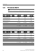
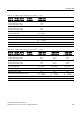

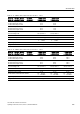
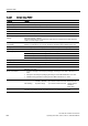
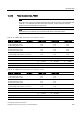
Table Of Contents
- Converter with CU230P-2 Control Units
- Legal information
- Changes in this manual
- Table of contents
- 1 Fundamental safety instructions
- 2 Introduction
- 3 Description
- 4 Installing
- 4.1 Overview of the inverter installation
- 4.2 Installing reactors, filters and braking resistors
- 4.3 Installing Power Module
- 4.4 Installing Control Unit
- 4.5 Connecting inverters in compliance with EMC
- 5 Commissioning
- 6 Adapting the terminal strip
- 7 Configuring the fieldbus
- 8 Setting functions
- 8.1 Overview of the inverter functions
- 8.2 Inverter control
- 8.2.1 Switching the motor on and off
- 8.2.2 Inverter control using digital inputs
- 8.2.3 Two-wire control: method 1
- 8.2.4 Two-wire control, method 2
- 8.2.5 Two-wire control, method 3
- 8.2.6 Three-wire control, method 1
- 8.2.7 Three-wire control, method 2
- 8.2.8 Running the motor in jog mode (JOG function)
- 8.2.9 Switching over the inverter control (command data set)
- 8.3 Setpoints
- 8.4 Setpoint calculation
- 8.5 Motor control
- 8.6 Protection and monitoring functions
- 8.7 Application-specific functions
- 8.7.1 Unit changeover
- 8.7.2 Calculating the energy saving
- 8.7.3 Electrically braking the motor
- 8.7.4 Flying restart – switching on while the motor is running
- 8.7.5 Automatic switch-on
- 8.7.6 Kinetic buffering (Vdc min control)
- 8.7.7 PID technology controller
- 8.7.8 Free technology controllers
- 8.7.9 Monitoring the load torque (system protection)
- 8.7.10 Load failure monitoring
- 8.7.11 Real time clock (RTC)
- 8.7.12 Time switch (DTC)
- 8.7.13 Record temperature via temperature-dependent resistances
- 8.7.14 Essential service mode
- 8.7.15 Multi-zone control
- 8.7.16 Bypass
- 8.7.17 Cascade control and hibernation mode
- 8.7.18 Free function blocks
- 8.8 Switchover between different settings
- 9 Backing up data and series commissioning
- 10 Corrective maintenance
- 10.1 Overview of replacing converter components
- 10.2 Replace Control Unit
- 10.3 Replacing the Control Unit without data backup
- 10.4 Replacing a Control Unit with active know-how protection
- 10.5 Replacing a Power Module
- 10.6 Upgrading the firmware
- 10.7 Firmware downgrade
- 10.8 Correcting an unsuccessful firmware upgrade or downgrade
- 10.9 If the converter no longer responds
- 11 Alarms, faults and system messages
- 12 Technical data
- A Appendix
- Index

Technical data
12.2 Technical data, Power Modules
Converter with CU230P-2 Control Units
Operating Instructions, 04/2014, FW V4.7, A5E34257946B AA
329
12.2.2.2
Power-dependent data, PM240
Note
The given input currents are valid for operation without a line reactor for a line voltage of 400
V with Vk = 1 % referred to the rated power of the inverter. If a l
ine reactor is used, the
specified values are reduced by a few percent.
Note
The values for Low Overload (LO) are identical with those of the rated values.
Table 12- 22 PM240, IP20, frame sizes A, 3-ph. 380 V AC… 480 V
Order No. - without filter
6SL3224-…
…0BE13-7UA0
…0BE15-5UA0
…0BE17-5UA0
LO base load power
LO base load input current
LO base load output current
0.37 kW
1.6 A
1.3 A
0.55 kW
2.0 A
1.7 A
0.75 kW
2.5 A
2.2 A
HO base load power
HO base load input current
HO base load output current
0.37 kW
1.6 A
1.3 A
0.55 kW
2.0 A
1.7 A
0.75 kW
2.5 A
2.2 A
Fuse according to UL (from SIEMENS)
Fuse according to UL (Class J, K-1 or K-5)
3NE1813-0, 16 A
10 A
3NE1813-0, 16 A
10 A
3NE1813-0, 16 A
10 A
Power loss
0.097 kW
0.099 kW
0.102 kW
Required cooling air flow
4.8 l/s
4.8 l/s
4.8 l/s
Cross section of line and motor cables 1 … 2.5 mm
2
18 … 14 AWG
1 … 2.5 mm
2
18 … 14 AWG
1 … 2.5 mm
2
18 … 14 AWG
Tightening torque for line and motor cables
0.5 Nm / 4 lbf in
0.5 Nm / 4 lbf in
0.5 Nm / 4 lbf in
Weight
1.2 kg
1.2 kg
1.2 kg
Table 12- 23 PM240, IP20, frame sizes A, 3-ph. 380 V AC… 480 V
Order No. - without filter
6SL3224-…
…0BE21-1UA0
…0BE21-5UA0
LO base load power
LO base load input current
LO base load output current
1.1 kW
3.9 A
3.1 A
1.5 kW
4.9 A
4.1 A
HO base load power
HO base load input current
HO base load output current
1.1 kW
3.8 A
3.1 A
1.5 kW
4.8 A
4.1 A
Fuse according to UL (from SIEMENS)
Fuse according to UL (Class J, K-1 or K-5)
3NE1813-0, 16 A
10 A
3NE1813-0, 16 A
10 A
Power loss
0.108 kW
0.114 kW
Required cooling air flow
4.8 l/s
4.8 l/s
Cross section of line and motor cables 1 … 2.5 mm
2
18 … 14 AWG
1 … 2.5 mm
2
18 … 14 AWG
Tightening torque for line and motor cables
0.5 Nm / 4 lbf in
0.5 Nm / 4 lbf in
Weight
1.1 kg
1.1 kg