
Operating Instructions
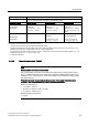

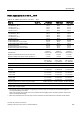


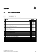
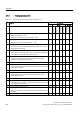
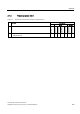
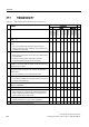
Table Of Contents
- Converter with CU230P-2 Control Units
- Legal information
- Changes in this manual
- Table of contents
- 1 Fundamental safety instructions
- 2 Introduction
- 3 Description
- 4 Installing
- 4.1 Overview of the inverter installation
- 4.2 Installing reactors, filters and braking resistors
- 4.3 Installing Power Module
- 4.4 Installing Control Unit
- 4.5 Connecting inverters in compliance with EMC
- 5 Commissioning
- 6 Adapting the terminal strip
- 7 Configuring the fieldbus
- 8 Setting functions
- 8.1 Overview of the inverter functions
- 8.2 Inverter control
- 8.2.1 Switching the motor on and off
- 8.2.2 Inverter control using digital inputs
- 8.2.3 Two-wire control: method 1
- 8.2.4 Two-wire control, method 2
- 8.2.5 Two-wire control, method 3
- 8.2.6 Three-wire control, method 1
- 8.2.7 Three-wire control, method 2
- 8.2.8 Running the motor in jog mode (JOG function)
- 8.2.9 Switching over the inverter control (command data set)
- 8.3 Setpoints
- 8.4 Setpoint calculation
- 8.5 Motor control
- 8.6 Protection and monitoring functions
- 8.7 Application-specific functions
- 8.7.1 Unit changeover
- 8.7.2 Calculating the energy saving
- 8.7.3 Electrically braking the motor
- 8.7.4 Flying restart – switching on while the motor is running
- 8.7.5 Automatic switch-on
- 8.7.6 Kinetic buffering (Vdc min control)
- 8.7.7 PID technology controller
- 8.7.8 Free technology controllers
- 8.7.9 Monitoring the load torque (system protection)
- 8.7.10 Load failure monitoring
- 8.7.11 Real time clock (RTC)
- 8.7.12 Time switch (DTC)
- 8.7.13 Record temperature via temperature-dependent resistances
- 8.7.14 Essential service mode
- 8.7.15 Multi-zone control
- 8.7.16 Bypass
- 8.7.17 Cascade control and hibernation mode
- 8.7.18 Free function blocks
- 8.8 Switchover between different settings
- 9 Backing up data and series commissioning
- 10 Corrective maintenance
- 10.1 Overview of replacing converter components
- 10.2 Replace Control Unit
- 10.3 Replacing the Control Unit without data backup
- 10.4 Replacing a Control Unit with active know-how protection
- 10.5 Replacing a Power Module
- 10.6 Upgrading the firmware
- 10.7 Firmware downgrade
- 10.8 Correcting an unsuccessful firmware upgrade or downgrade
- 10.9 If the converter no longer responds
- 11 Alarms, faults and system messages
- 12 Technical data
- A Appendix
- Index

Technical data
12.2 Technical data, Power Modules
Converter with CU230P-2 Control Units
Operating Instructions, 04/2014, FW V4.7, A5E34257946B AA
353
PM330, frame size HX, 3 AC 380 V … 480 V
Table 12- 48 PM330, frame size HX, 3 AC 380 V … 480 V
Order no.
6SL3310…
…1PE35-8AA0
…1PE36-6AA0
…1PE37-4AA0
Rated input current
- for 380/400 V, 40° C
- for 480 V, 40° C
- for 380/400 V, 50° C
- for 480 V, 50° C
597 A
497 A
507A
422 A
668 A
536 A
568 A
456 A
750 A
614 A
637 A
522 A
Rated output current I
N
- for 380/400 V, 40° C
- for 480 V, 40° C
- for 380/400 V, 50° C
- for 480 V, 50° C
585 A
487 A
497 A
414 A
655 A
526 A
557 A
447 A
735 A
602 A
625 A
512 A
LO base-load power
LO base-load input current at 400 V
LO base-load output current at 400 V
315 kW
581 A
570 A
355 kW
653 A
640 A
400 kW
734 A
720 A
HO base-load power
HO base-load input current at 400 V
HO base-load output current at 400 V
250 kW
477 A
468 A
250 kW
501 A
491 A
315 kW
562 A
551 A
Fuse according to IEC
manufacturer:
Maximum permissible line short-circuit current I
kmax
Minimum network short-circuit current required I
kmin
1)
3NE1437-2 (710
A/690 V)
Siemens AG
≤ 100 kA
> 9.0 kA
3NE1438-2 (800
A/690 V)
Siemens AG
≤ 100 kA
> 10.0 kA
3NE1448-2 (850
A/690 V)
Siemens AG
≤ 100 kA
> 12.0 kA
Fuse according to UL
2)
Class L
650 A / 600 V
e. g. KTU 650
Class L
700 A / 600 V
e. g. KTU 700
Class L
800 A / 600 V
e. g. KTU 800
max.power loss, at I
N
, 40 °C, 400 V
6.791 kW
7.687 kW
8.385 kW
Required cooling air flow
360 l/s
360 l/s
360 l/s
Maximum connectable cross-section of the line, motor and DC-
link cable
4 x 240 mm
2
4 x 500 kcmil
4 x 240 mm
2
4 x 500 kcmil
4 x 240 mm
2
4 x 500 kcmil
Recommended cable cross-section for 380/400 V
- power cable
- motor cable
2 x 240 mm
2
2 x 185 mm²
3 x 150 mm
2
2 x 240 mm²
3 x 185 mm
2
2 x 240 mm²
Recommended cable cross-section for 480 V
- power cable
- motor cable
2 x 185 mm
2
2 x 150 mm²
2 x 240 mm
2
2 x 185 mm²
2 x 240 mm
2
2 x 240 mm²
Tightening torque for line, motor and ground cable
50 Nm / 443 lbf in
50 Nm / 443 lbf in
50 Nm / 443 lbf in
Weight 155 kg 155 kg 157 kg
Minimum control cabinet size for installation of the Power
Module (width x height x depth)
800 mm x 2000 mm x 600 mm
1)
The network supply must be capable of supplying the minimum short-circuit current so that the fuses trigger and
consequential damage is avoided.
Note: If the minimum short-circuit current is not reached then the tripping time for the fuses increases, and this may
result in consequential damage.
2)
When semi-conductor fuses are used, they must be mounted in the same lower-level construction as the inverter.