
Operating Instructions
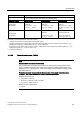

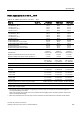
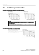


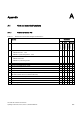
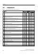
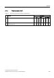
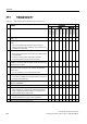
Table Of Contents
- Converter with CU230P-2 Control Units
- Legal information
- Changes in this manual
- Table of contents
- 1 Fundamental safety instructions
- 2 Introduction
- 3 Description
- 4 Installing
- 4.1 Overview of the inverter installation
- 4.2 Installing reactors, filters and braking resistors
- 4.3 Installing Power Module
- 4.4 Installing Control Unit
- 4.5 Connecting inverters in compliance with EMC
- 5 Commissioning
- 6 Adapting the terminal strip
- 7 Configuring the fieldbus
- 8 Setting functions
- 8.1 Overview of the inverter functions
- 8.2 Inverter control
- 8.2.1 Switching the motor on and off
- 8.2.2 Inverter control using digital inputs
- 8.2.3 Two-wire control: method 1
- 8.2.4 Two-wire control, method 2
- 8.2.5 Two-wire control, method 3
- 8.2.6 Three-wire control, method 1
- 8.2.7 Three-wire control, method 2
- 8.2.8 Running the motor in jog mode (JOG function)
- 8.2.9 Switching over the inverter control (command data set)
- 8.3 Setpoints
- 8.4 Setpoint calculation
- 8.5 Motor control
- 8.6 Protection and monitoring functions
- 8.7 Application-specific functions
- 8.7.1 Unit changeover
- 8.7.2 Calculating the energy saving
- 8.7.3 Electrically braking the motor
- 8.7.4 Flying restart – switching on while the motor is running
- 8.7.5 Automatic switch-on
- 8.7.6 Kinetic buffering (Vdc min control)
- 8.7.7 PID technology controller
- 8.7.8 Free technology controllers
- 8.7.9 Monitoring the load torque (system protection)
- 8.7.10 Load failure monitoring
- 8.7.11 Real time clock (RTC)
- 8.7.12 Time switch (DTC)
- 8.7.13 Record temperature via temperature-dependent resistances
- 8.7.14 Essential service mode
- 8.7.15 Multi-zone control
- 8.7.16 Bypass
- 8.7.17 Cascade control and hibernation mode
- 8.7.18 Free function blocks
- 8.8 Switchover between different settings
- 9 Backing up data and series commissioning
- 10 Corrective maintenance
- 10.1 Overview of replacing converter components
- 10.2 Replace Control Unit
- 10.3 Replacing the Control Unit without data backup
- 10.4 Replacing a Control Unit with active know-how protection
- 10.5 Replacing a Power Module
- 10.6 Upgrading the firmware
- 10.7 Firmware downgrade
- 10.8 Correcting an unsuccessful firmware upgrade or downgrade
- 10.9 If the converter no longer responds
- 11 Alarms, faults and system messages
- 12 Technical data
- A Appendix
- Index

Appendix
A.2 Star-delta motor connection and application examples
Converter with CU230P-2 Control Units
360 Operating Instructions, 04/2014, FW V4.7, A5E34257946B AA
A.1.4
Firmware version 4.7
Table A- 4 New functions and function changes in Firmware 4.7
Function
SINAMICS
G120
G120D
1 Supporting the identification & maintenance datasets
(I&M1 … 4)
✓ ✓ ✓ ✓ ✓ ✓ ✓ ✓ ✓
2 Fall in pulse rate with increased drive power required by the
motor
• The inverter temporarily lowers the pulse frequency if
required when the motor is started up, and simultaneously
increases the current limit.
✓ ✓ ✓ ✓ ✓ ✓ ✓ ✓ ✓
3 S7 communication
• Direct data exchange from the inverter and human machine
interface (HMI)
• Increase in communication performance with the
engineering tools and support of the S7 routing
✓ ✓ ✓ ✓ ✓ ✓ ✓ ✓ -
4 The basic functions of Safety Integrated are unrestrictedly
available in all control types with 1FK7 encoderless permanent-
field synchronous motors
- - - - - - ✓ - -
5 Direct selection of the 1FK7 encoderless permanent-field
synchronous motors using the order number with allocated
code number
• It is not necessary to input individual motor data
- - - - - - ✓ - -
6 Pulse input as source of setpoint value
• The inverter calculates its speed setpoint from a sequence
of pulses at the digital input.
- - - - - ✓ - - -
7 Dynamic IP address assignment (DHCP) and temporary device
names for PROFINET
✓ ✓ ✓ - ✓ ✓ ✓ ✓ ✓
8
PROFIenergy Slave profile 2 and 3
✓
✓
✓
-
✓
✓
✓
✓
✓
9 Uniform behavior for component replacement
• After a component is replaced, an inverter with activated
Safety Integrated will report what type of component has
been replaced using a unique code.
✓ ✓ - - ✓ ✓ ✓ ✓ ✓
10 Improved direct-component control in PM230
• Optimized efficiency for pump and fan applications
- - ✓ - - - - - -
11
Rounding down of BACnet and macros
-
-
✓
-
-
-
-
-
-