
Operating Instructions
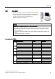
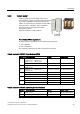
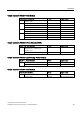
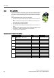
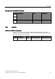
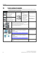
Table Of Contents
- Converter with CU230P-2 Control Units
- Legal information
- Changes in this manual
- Table of contents
- 1 Fundamental safety instructions
- 2 Introduction
- 3 Description
- 4 Installing
- 4.1 Overview of the inverter installation
- 4.2 Installing reactors, filters and braking resistors
- 4.3 Installing Power Module
- 4.4 Installing Control Unit
- 4.5 Connecting inverters in compliance with EMC
- 5 Commissioning
- 6 Adapting the terminal strip
- 7 Configuring the fieldbus
- 8 Setting functions
- 8.1 Overview of the inverter functions
- 8.2 Inverter control
- 8.2.1 Switching the motor on and off
- 8.2.2 Inverter control using digital inputs
- 8.2.3 Two-wire control: method 1
- 8.2.4 Two-wire control, method 2
- 8.2.5 Two-wire control, method 3
- 8.2.6 Three-wire control, method 1
- 8.2.7 Three-wire control, method 2
- 8.2.8 Running the motor in jog mode (JOG function)
- 8.2.9 Switching over the inverter control (command data set)
- 8.3 Setpoints
- 8.4 Setpoint calculation
- 8.5 Motor control
- 8.6 Protection and monitoring functions
- 8.7 Application-specific functions
- 8.7.1 Unit changeover
- 8.7.2 Calculating the energy saving
- 8.7.3 Electrically braking the motor
- 8.7.4 Flying restart – switching on while the motor is running
- 8.7.5 Automatic switch-on
- 8.7.6 Kinetic buffering (Vdc min control)
- 8.7.7 PID technology controller
- 8.7.8 Free technology controllers
- 8.7.9 Monitoring the load torque (system protection)
- 8.7.10 Load failure monitoring
- 8.7.11 Real time clock (RTC)
- 8.7.12 Time switch (DTC)
- 8.7.13 Record temperature via temperature-dependent resistances
- 8.7.14 Essential service mode
- 8.7.15 Multi-zone control
- 8.7.16 Bypass
- 8.7.17 Cascade control and hibernation mode
- 8.7.18 Free function blocks
- 8.8 Switchover between different settings
- 9 Backing up data and series commissioning
- 10 Corrective maintenance
- 10.1 Overview of replacing converter components
- 10.2 Replace Control Unit
- 10.3 Replacing the Control Unit without data backup
- 10.4 Replacing a Control Unit with active know-how protection
- 10.5 Replacing a Power Module
- 10.6 Upgrading the firmware
- 10.7 Firmware downgrade
- 10.8 Correcting an unsuccessful firmware upgrade or downgrade
- 10.9 If the converter no longer responds
- 11 Alarms, faults and system messages
- 12 Technical data
- A Appendix
- Index

Description
3.5 Tools to commission the converter
Converter with CU230P-2 Control Units
40 Operating Instructions, 04/2014, FW V4.7, A5E34257946B AA
3.5
Tools to commission the converter
The following tools are used to commission, troubleshoot and control the inverter, as well as
to backup and transfer the inverter settings.
Operator panels
Order number
BOP-2 (Basic Operator Panel) -
for snapping onto the inverter
• Two-line display
• Guided basic
commissioning
Door mounting kit for
IOP/BOP-2
• For installation of the
BOP-2 or IOP in a
control cabinet door.
• Degree of protection
with IOP: IP54 or
UL Type 12
• Degree of protection
with BOP-2: IP55
BOP-2:
6SL3255-0AA00-4CA1
IOP:
6SL3255-0AA00-4JA0
Door mounting kit:
6SL3256-0AP00-0JA0
IOP (Intelligent Operator Panel)
- for snapping onto the inverter
• Plain text display
• Menu-based operation and
application wizards
For mobile use of the IOP:
IOP handheld with power supply unit and rechargeable
batteries as well as RS232 connection cable
If you are using your own connection cable, carefully note the
maximum permissible length of 5 m.
6SL3255-0AA00-4HA0
PC tools
STARTER
Connected to the inverter via USB port, PROFIBUS or
PROFINET
Download: STARTER
(http://support.automation.siemens.com/WW/view/en/108049
85/130000)
STARTER on DVD:
6SL3072-0AA00-0AG0
Startdrive
Connected to the inverter via USB port, PROFIBUS or
PROFINET
Download: Startdrive
(http://support.automation.siemens.com/WW/view/en/680345
68)
Startdrive on DVD:
6SL3072-4CA02-1XG0
SINAMICS PC Inverter Connection Kit 2
Contains the correct USB cable (3 m) to connect a PC to the
inverter.
6SL3255-0AA00-2CA0