
Operating Instructions
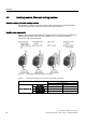
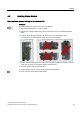
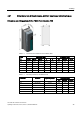
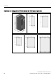
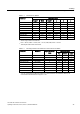
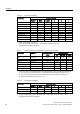
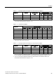
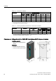
Table Of Contents
- Converter with CU230P-2 Control Units
- Legal information
- Changes in this manual
- Table of contents
- 1 Fundamental safety instructions
- 2 Introduction
- 3 Description
- 4 Installing
- 4.1 Overview of the inverter installation
- 4.2 Installing reactors, filters and braking resistors
- 4.3 Installing Power Module
- 4.4 Installing Control Unit
- 4.5 Connecting inverters in compliance with EMC
- 5 Commissioning
- 6 Adapting the terminal strip
- 7 Configuring the fieldbus
- 8 Setting functions
- 8.1 Overview of the inverter functions
- 8.2 Inverter control
- 8.2.1 Switching the motor on and off
- 8.2.2 Inverter control using digital inputs
- 8.2.3 Two-wire control: method 1
- 8.2.4 Two-wire control, method 2
- 8.2.5 Two-wire control, method 3
- 8.2.6 Three-wire control, method 1
- 8.2.7 Three-wire control, method 2
- 8.2.8 Running the motor in jog mode (JOG function)
- 8.2.9 Switching over the inverter control (command data set)
- 8.3 Setpoints
- 8.4 Setpoint calculation
- 8.5 Motor control
- 8.6 Protection and monitoring functions
- 8.7 Application-specific functions
- 8.7.1 Unit changeover
- 8.7.2 Calculating the energy saving
- 8.7.3 Electrically braking the motor
- 8.7.4 Flying restart – switching on while the motor is running
- 8.7.5 Automatic switch-on
- 8.7.6 Kinetic buffering (Vdc min control)
- 8.7.7 PID technology controller
- 8.7.8 Free technology controllers
- 8.7.9 Monitoring the load torque (system protection)
- 8.7.10 Load failure monitoring
- 8.7.11 Real time clock (RTC)
- 8.7.12 Time switch (DTC)
- 8.7.13 Record temperature via temperature-dependent resistances
- 8.7.14 Essential service mode
- 8.7.15 Multi-zone control
- 8.7.16 Bypass
- 8.7.17 Cascade control and hibernation mode
- 8.7.18 Free function blocks
- 8.8 Switchover between different settings
- 9 Backing up data and series commissioning
- 10 Corrective maintenance
- 10.1 Overview of replacing converter components
- 10.2 Replace Control Unit
- 10.3 Replacing the Control Unit without data backup
- 10.4 Replacing a Control Unit with active know-how protection
- 10.5 Replacing a Power Module
- 10.6 Upgrading the firmware
- 10.7 Firmware downgrade
- 10.8 Correcting an unsuccessful firmware upgrade or downgrade
- 10.9 If the converter no longer responds
- 11 Alarms, faults and system messages
- 12 Technical data
- A Appendix
- Index

Installing
4.3 Installing Power Module
Converter with CU230P-2 Control Units
44 Operating Instructions, 04/2014, FW V4.7, A5E34257946B AA
Mounting Power Modules using through-hole technology
We recommend that you use the optionally available mounting frame to mount the push-
through unit in a control cabinet. This mounting frame includes the necessary seals and
frame to ensure compliance with degree of protection IP54.
If you do not use the optional mounting frames, then you must ensure that the required
degree of protection is complied with using other appropriate measures.
You must mount the inverter on unpainted metal surfaces in order to comply with EMC
requirements.
Procedure
Proceed as follows to correctly mount the Power Module:
1.
Prepare the cutout and the mounting holes for the Power
Module and the mounting frame corresponding to the
dimension drawings of the mounting frame.
Also note that the PT Power modules must be vertically
mounted with the line and motor connections facing
downwards.
2.
Position the mounting frame at the rear of the control
cabinet and attach it to the control cabinet by tightening
the corresponding screws by hand.
3.
Attach the seal to the inner side of the control cabinet.
4.
Mount the frequency inverter and initially tighten all of
the mounting screws by hand.
5.
Tighten the screws with a torque of 3 Nm.
Mounting frame
You have correctly mounted the Power Module.
Mounting additional components
Depending on the application, the following additional components, for example, may be
required (also refer to Section Description (Page 23)):
● Line reactors
● Filter
● Braking resistors
● Brake Relay
Information about mounting these components is provided in the instructions supplied.