
Operating Instructions

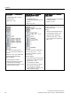
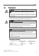
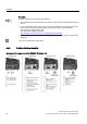
Table Of Contents
- Converter with CU230P-2 Control Units
- Legal information
- Changes in this manual
- Table of contents
- 1 Fundamental safety instructions
- 2 Introduction
- 3 Description
- 4 Installing
- 4.1 Overview of the inverter installation
- 4.2 Installing reactors, filters and braking resistors
- 4.3 Installing Power Module
- 4.4 Installing Control Unit
- 4.5 Connecting inverters in compliance with EMC
- 5 Commissioning
- 6 Adapting the terminal strip
- 7 Configuring the fieldbus
- 8 Setting functions
- 8.1 Overview of the inverter functions
- 8.2 Inverter control
- 8.2.1 Switching the motor on and off
- 8.2.2 Inverter control using digital inputs
- 8.2.3 Two-wire control: method 1
- 8.2.4 Two-wire control, method 2
- 8.2.5 Two-wire control, method 3
- 8.2.6 Three-wire control, method 1
- 8.2.7 Three-wire control, method 2
- 8.2.8 Running the motor in jog mode (JOG function)
- 8.2.9 Switching over the inverter control (command data set)
- 8.3 Setpoints
- 8.4 Setpoint calculation
- 8.5 Motor control
- 8.6 Protection and monitoring functions
- 8.7 Application-specific functions
- 8.7.1 Unit changeover
- 8.7.2 Calculating the energy saving
- 8.7.3 Electrically braking the motor
- 8.7.4 Flying restart – switching on while the motor is running
- 8.7.5 Automatic switch-on
- 8.7.6 Kinetic buffering (Vdc min control)
- 8.7.7 PID technology controller
- 8.7.8 Free technology controllers
- 8.7.9 Monitoring the load torque (system protection)
- 8.7.10 Load failure monitoring
- 8.7.11 Real time clock (RTC)
- 8.7.12 Time switch (DTC)
- 8.7.13 Record temperature via temperature-dependent resistances
- 8.7.14 Essential service mode
- 8.7.15 Multi-zone control
- 8.7.16 Bypass
- 8.7.17 Cascade control and hibernation mode
- 8.7.18 Free function blocks
- 8.8 Switchover between different settings
- 9 Backing up data and series commissioning
- 10 Corrective maintenance
- 10.1 Overview of replacing converter components
- 10.2 Replace Control Unit
- 10.3 Replacing the Control Unit without data backup
- 10.4 Replacing a Control Unit with active know-how protection
- 10.5 Replacing a Power Module
- 10.6 Upgrading the firmware
- 10.7 Firmware downgrade
- 10.8 Correcting an unsuccessful firmware upgrade or downgrade
- 10.9 If the converter no longer responds
- 11 Alarms, faults and system messages
- 12 Technical data
- A Appendix
- Index

Installing
4.5 Connecting inverters in compliance with EMC
Converter with CU230P-2 Control Units
Operating Instructions, 04/2014, FW V4.7, A5E34257946B AA
79
4.5
Connecting inverters in compliance with EMC
4.5.1
EMC-compliant connection of the converter
EMC-compliant installation of the inverter and motor are required in order to ensure
disturbance-free operation of the drive.
Install and operate inverters with IP20 degree of protection in a closed control cabinet.
Inverters with degree of protection IP55 are suitable for installation outside a control cabinet.
An overview of control cabinet installation and cabling can be found in the following section.
For further details, refer to the installation instructions of the Power Module.
The EMC-compliant connection of the inverter itself is described in the following sections.
4.5.2
Avoiding electromagnetic influence (EMI)
The inverters are designed for operation in industrial environments where high values of EMI
are expected. Safe, reliable and disturbance-free operation is only guaranteed if the devices
are installed by appropriately trained and qualified personnel.
Control cabinet design
● Connect the metallic parts and components of the control cabinet to the frame of the
cabinet through a good electrical connection.
– Side panels
– Rear panels
– Cover plate
– Base plates
Use the largest possible contact area or many individual screw connections.
● Connect the PE busbar and EMC shielding bus to the control cabinet frame using a good
electrical connection established through the largest possible surface area.
● Connect all metal enclosures of the devices installed in the control cabinet (such as the
inverter and line filter) to the control cabinet frame through a good electrical connection
established through the largest possible surface area.
We recommend that these devices are mounted on a bare metal plate with good
conducting properties.