
Operating Instructions
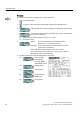
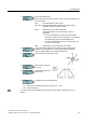
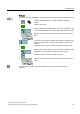
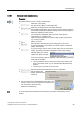
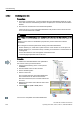
Table Of Contents
- Converter with CU230P-2 Control Units
- Legal information
- Changes in this manual
- Table of contents
- 1 Fundamental safety instructions
- 2 Introduction
- 3 Description
- 4 Installing
- 4.1 Overview of the inverter installation
- 4.2 Installing reactors, filters and braking resistors
- 4.3 Installing Power Module
- 4.4 Installing Control Unit
- 4.5 Connecting inverters in compliance with EMC
- 5 Commissioning
- 6 Adapting the terminal strip
- 7 Configuring the fieldbus
- 8 Setting functions
- 8.1 Overview of the inverter functions
- 8.2 Inverter control
- 8.2.1 Switching the motor on and off
- 8.2.2 Inverter control using digital inputs
- 8.2.3 Two-wire control: method 1
- 8.2.4 Two-wire control, method 2
- 8.2.5 Two-wire control, method 3
- 8.2.6 Three-wire control, method 1
- 8.2.7 Three-wire control, method 2
- 8.2.8 Running the motor in jog mode (JOG function)
- 8.2.9 Switching over the inverter control (command data set)
- 8.3 Setpoints
- 8.4 Setpoint calculation
- 8.5 Motor control
- 8.6 Protection and monitoring functions
- 8.7 Application-specific functions
- 8.7.1 Unit changeover
- 8.7.2 Calculating the energy saving
- 8.7.3 Electrically braking the motor
- 8.7.4 Flying restart – switching on while the motor is running
- 8.7.5 Automatic switch-on
- 8.7.6 Kinetic buffering (Vdc min control)
- 8.7.7 PID technology controller
- 8.7.8 Free technology controllers
- 8.7.9 Monitoring the load torque (system protection)
- 8.7.10 Load failure monitoring
- 8.7.11 Real time clock (RTC)
- 8.7.12 Time switch (DTC)
- 8.7.13 Record temperature via temperature-dependent resistances
- 8.7.14 Essential service mode
- 8.7.15 Multi-zone control
- 8.7.16 Bypass
- 8.7.17 Cascade control and hibernation mode
- 8.7.18 Free function blocks
- 8.8 Switchover between different settings
- 9 Backing up data and series commissioning
- 10 Corrective maintenance
- 10.1 Overview of replacing converter components
- 10.2 Replace Control Unit
- 10.3 Replacing the Control Unit without data backup
- 10.4 Replacing a Control Unit with active know-how protection
- 10.5 Replacing a Power Module
- 10.6 Upgrading the firmware
- 10.7 Firmware downgrade
- 10.8 Correcting an unsuccessful firmware upgrade or downgrade
- 10.9 If the converter no longer responds
- 11 Alarms, faults and system messages
- 12 Technical data
- A Appendix
- Index

Commissioning
5.4 Basic commissioning
Converter with CU230P-2 Control Units
92 Operating Instructions, 04/2014, FW V4.7, A5E34257946B AA
Procedure
To enter the data for basic commissioning, proceed as follows:
1.
Press the ESC key.
2.
Press one of the arrow keys until the BOP
-2 displays the "SETUP" menu.
3.
In the "SETUP" menu, press the OK key to start basic commissioning.
4.
If you wish to restore all of the param
eters to the factory setting before
the basic commissioning:
4.1.
Switch over the display using an arrow key: nO → YES
4.2.
Press the OK key.
5.
VF LIN
V/f
control with a linear characteristic for basic
applications, e.g. horizontal conveyors.
VF QUAD
V/f control with a square
-law characteristic for basic
pump and fan applications.
SPD N EN
We recommend that you use vector control.
Further information on the control types can be found in Section
Selecting the control mode (Page 88)
6.
Transfer the data from the motor rating plate to the inverter:
6.1.
Motor standard
KW 50HZ
IEC
HP 60HZ
NEMA
KW 60HZ
IEC 60 Hz
6.2.
Rated voltage
6.3.
Rated current
6.4.
IEC power (kW)
NEMA (HP)
6.5.
Rated speed