The worldwide standard for home and building control Manual for KNX Planning siemens.
Optimum control requires accurate measurements This manual was written by practitioners for practitioners and has become a popular and indispensable reference book over the last few years. Legal regulations increasingly appeal for the economic use of energy. At the same time, the indoor climate must meet stringent requirements. Both requirements can be fully met only if all necessary measured data are available and the sensors remain absolutely reliable year after year.
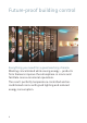
Future-proof building control Everything you need for a good working climate Working concentrated while saving energy – products from Siemens improve the atmosphere in rooms and facilitate more economical operations. The result: perfectly temperature-controlled and airconditioned rooms with good lighting and reduced energy consumption.
Highlights • Saves up to 30 percent energy with individual room control and energy saving functions • Protects investments on the basis of reliable products and the ability to add KNX devices • Easy commissioning and adaptation to changes in use due to tested applications • Extremely environmentally friendly due to energyindependent variants with EnOcean technology Contact and support GAMMA instabus: siemens.com/gamma Technical documentation: siemens.com/gamma-td HVAC Integrated Tool (HIT): siemens.
Contents Bus systems............................................................
Mounting guidelines for sensors............................
Application examples.............................................
Constant light level control 75 Sunlight tracking control 76 Shadow tracking control 78 Sunlight tracking control with shadow tracking control 79 Wiring of lighting groups with DALI 80 DALI topology with sensors 82 Switching off standby with DALI 83 Wireless remote control (KNX/EnOcean) 84 Web-based visualization 86 Integrating KNX into BACnet 88 Glossary..................................................................
Bus systems • Communication standards 12 • KNX – description, highlights and system data 14 • DALI – description, highlights and system data 18 • EnOcean – description, highlights and system data 22 • BACnet – description and highlights 26 • KNX PL-Link – description and highlights 28 • Further communication standards – Modbus, M-Bus, OPC, Web, ZigBee 30 11
Communication standards In building control, open communication is important. It allows easy and secure integration of devices, systems and functions. Support for multiple open standards ensures communication and facilitates efficient engineering. It also makes system maintenance and interoperability easier, thereby providing greater investment protection. Siemens supports different communication protocols in building automation. As a result, a wide range of communicating devices can be used.
Bus systems Highlights • Easy and secure integration • Reliable data exchange between various communication systems • Comfortable and universal operation • Long-term investment protection
KNX The KNX technology allows flexible implementation and expansion of both simple as well as cross-discipline solutions in room and building automation according to individual requirements. KNX products for controlling lighting, sun protection and room climate as well as for energy management and security functions are characterized by easy installation and commissioning. The vendor-independent ETS Tool is used for commissioning.
Highlights • Harmonized products and systems for cross-discipline building and room automation • Easy integration into higher-level building management systems on the basis of the open communication standard • Uniform commissioning, due to the use of vendor- and product-independent commissioning software (ETS) • A well-known system that is widely used in building control with guaranteed interoperability thanks to certification processes • Corresponds to the previous European Installation Bus (EIB) and is b
System data Bus connection Cable type YCYM 2 × 2 × 0.8 mm2 one wire pair (red, black) for signal transmission and power supply, one wire pair (yellow, white) for additional applications (SELV or voice) Cable lengths Total length of one line max. 1,000 m (wire diameter: 0.8 mm) (including all branches) Length between two bus devices max. 700 m Length between a bus device and the power supply max.
Transmission Transmission technology decentralized, event-controlled, serial, symmetrical Baud rate 9,600 bit/s Device properties Protection class acc.
DALI DALI (Digital Addressable Lighting Interface) is a standardized interface for lighting control. Electronic ballasts, transformers and sensors in a lighting system communicate with the building automation system via DALI. DALI is an internationally applied standard compliant with IEC 62386 requirements. For further information, please visit: dali-ag.
System data Bus connection Cable type NYM 5 x 1.5 mm2 for mains power input and DALI, excluding the polarity. Ballast and control device can be operated at different line voltage phases. Cable lengths The length of the Maximum voltage drop on the cable is control line is limited 2 V at 250 mA. The maximum total cable only by the voltage drop length between the control unit and the connected ballasts is 300 m. Cable cross-section A is calculated from the following formula: L: Cable length (m) I: Max.
Bus devices Possible addresses max. 64 Possible groups max. 16 Number of bus devices per line max. 64 ballasts and 64 sensors Number of possible scenes per ballast Up to 16 light values (scenes) per ballast can be stored, regardless of any group assignments that may be programmed. Topology Parallel, star-shaped wiring, excluding possible groups. Ring-shaped wiring is not permitted. Terminating resistors are not needed.
Transmission Transmission technology serial, asynchronous Baud rate 1,200 bit/s Device properties Protection class EN 60529 (DIN VDE 0470-1) and DIN EN 50102 Safety measures Basic insulation required according to IEC 60928 EMC requirements EN 50081/VDE 0839-81 and EN 50082/VDE 0839-82 Ballast standards Safety (EN 61347) Functionality (EN 60929) Line current harmonics (EN 61000-3-2) Radio interference suppression from 9 kHz to 300 MHz (EN 55015:2006 + A1:2007)/CDN measurement Immunity (EN 61547) Co
EnOcean Leading global companies in the building industry formed the EnOcean Alliance to implement innovative wireless solutions for sustainable building projects. The core technology is EnOcean’s battery-free wireless technology for maintenance-free sensor solutions that can be flexibly positioned. The EnOcean Alliance promotes the further development of the interoperable standard as well as the future viability of innovative wireless sensor technology.
Highlights • EnOcean combines wireless communication with power generation methods • Access to a large number of easy-to-integrate field devices, due to standardized EnOcean communications • Environmentally friendly because no batteries need to be disposed of, and because of low radiant energy, which is even less than with wired sensors • Maintenance-free • Short installation times • Reduces fire load 23 Bus systems Product portfolio from Siemens with EnOcean communication • GAMMA instabus, EnOcean sen
System data Bus connection Radio frequency 315 MHz (Asia), 868 MHz (EU countries and China), 902 MHz (USA and Canada) and 928 MHz (Japan) Ranges … dependent on the nature of the building Range reduction due to wall materials against free-field propagation (300 m): • Wood, plaster, uncoated glass, without metal 0 – 10% • Brick, pressed wood 5 – 35% • Concrete with iron reinforcement 10 – 90% Bus devices Number of transmitters/ transmit protocols 500/minute (99.
Safety measures Device-dependent Coexistence with other wireless systems No interference with WLAN and PMR systems, etc.
BACnet The communication protocol BACnet was specially developed to meet the needs of buildings, both inside and out. It is well suited for the automation level as well as the management level. It is primarily for HVAC systems as well as fire control panels, intrusion detection and access control systems. BACnet is continuously expanded to accommodate additional building-specific systems such as escalators and elevators. Some 900 manufacturers use BACnet in their products.
Highlights • Maximum investment security through use of the open, international standard ISO 16484-5 • Manufacturer-independent • No license costs • Guaranteed reliability thanks to independent testing and certification bodies for BACnet devices • Wide range of transmission media such as BACnet IP or BACnet MS/TP can be combined as needed, and support extremely flexible topologies • Integration of widely diverse disciplines and manufacturers without need for specialized hardware 27 Bus systems Product po
KNX PL-Link KNX PL-Link (PeripheraL-Link) is a Desigo-specific bus system optimized to enable communication between distributed, i.e. decentrally installed field devices and the modular PXC3 room automation stations. Its typical areas of application include controlling all disciplines within a room, such as heating, ventilation, air conditioning, lighting and sun protection.
Highlights • Plug-and-play bus system with automatic device recognition • Bus cable for up to 64 devices in linear or star topologies with a maximum line length of 1,000 m • Power supply for up to 64 devices directly via the bus cable • Fast, event-oriented communication for lighting and sun protection applications 29 Bus systems Devices from Siemens with KNX PL-Link function • Modular room automation stations Desigo PXC3 • QMX3 room operator units • VAV compact controllers GDB/GLB181 • Gamma products, e
Other communication standards Modbus Modbus is an open, widely used standard employed in many areas of application such as industry, buildings as well as the transport and energy sectors. The Modbus protocol is used to establish master-slave/client-server communication between intelligent devices. Via Modbus, a master, for example an automation station, and multiple slaves, such as refrigeration machines, can be connected.
protected two-wire cable from the connected slaves, i.e. measuring instruments, to a master. M-Bus meters are available for heat, water, electricity and gas. Please find more information at: m-bus.com 31 Bus systems OPC OPC is a standardized software interface that enables data exchange between various devices, control systems and applications of differing manufacturers.
Web (IT standard technology) This is the umbrella term for a number of standardized communication protocols in the IT world that can be used within a local facility as well as via the Internet. It includes protocols that enable users to communicate with their plants and products, such as graphic user interfaces operable with Web browsers, e-mail messages to maintenance personnel or loading firmware modifications.
Bus systems ZigBee ZigBee is a specification for wireless short-range radio networks that handle only low data volumes, used for example in sensor networks and lighting system engineering. The ZigBee Alliance is an international pool of various business enterprises. ZigBee is based on the IEEE 802.15.4 standard. Please find more infor mation at: zigbee.
Mounting guidelines for sensors • Outdoor temperature sensors 36 • Motion and presence detectors 38 • Brightness sensors 40 • Installation zones 42 • Room sensors for temperature, humidity and air quality 44 • Outdoor brightness sensors 46 • Wind sensors 47 • Door/window contacts 48 • Weather stations/sensors (brightness, precipitation, temperature) 50 • Immersion temperature sensors 51 • Strap-on temperature sensors 52 • Strap-on and immersion temperature senso
Outdoor temperature sensors Mounting guidelines for outdoor temperature sensors • Do not expose to direct sunlight • Do not mount on facades with a great deal of ascending heat • Do not attach to walls in front of a chimney • Do not mount on eaves or a balcony • Do not place over windows • Do no mount over ventilation shafts • Do not paint over sensors • Mount sensors in an accessible location to allow easy inspection and maintenance 36
Depending on the application, place outdoor temperature sensors as follows: For control The sensors should be mounted on the building’s outer wall with the windows of the main living areas. However, they should not be exposed to morning sunlight. In case of doubt, you can mount these sensors on the north or northwest wall. 3m 37 Mounting guidelines N For optimization Always attach the sensors to the building wall that faces away from the sun, which is normally on the north side.
Motion and presence detectors Mounting guidelines for motion and presence detectors in a room • Do not expose motion detectors to direct sunlight • Do not mount any lamps within the detection zone • Avoid placing any sources of rapid temperature changes within the detection zone, e.g.
Mounting guidelines 39
Brightness sensors Mounting guidelines for brightness sensors • Make sure that the brightness sensor measures only indirect, reflected light; direct sunlight distorts the measurement results • Avoid shiny surfaces that are highly reflective, as this interferes with measurement • Avoid surfaces that are too dark with low light reflection properties, as this impedes measurement of the current brightness level • Keep in mind that thermal protection glass can influence the daylight measurement; the tripping va
Mounting guidelines 41
Installation zones 15 cm 150 cm 110 cm 30 cm Standard switch and socket heights • Power sockets: 30 cm • Linking duct: 100 cm • Switches and pushbuttons: 110 cm • Room thermostats and touch-display devices: 150 cm Tips for cable routing • Cables should be routed in a way that the positioning and sheathing prevent mechanical damage to the cables • Cables in walls should only be routed either vertically or horizontally • Cabling laid in a fixed position is safer than cabling that can move 42
30 cm 15 cm • Route cables so that they are out of people’s reach • Route cables at an adequate distance from hot piping, lightning protection systems and telecom munication lines • In horizontal cable runs: lay the cable preferably at 30 cm below the ceiling level, and at either 30 or 100 cm above the floor level • In vertical cable runs: lay the cable preferably at 15 cm to the side of the building carcass (shell) edges or corners Source: DIN 18015 43 Mounting guidelines 100 cm
Room sensors for temperature, humidity and air quality Mounting guidelines for sensors measuring room temperature, relative humidity and air quality • Mount sensors in rooms at a height of approx. 1.
In products from Siemens, the sensors within the devices are located before the wall so that the rising air flow can be accurately measured. To ensure accurate readings, it is a good idea to keep the following in mind during installation: Clearances between the cable (4) or plastic hose and the installation pipe (5) need to be sealed. Otherwise, inefficient air circulation will occur, causing measuring errors.
Outdoor brightness sensors 3m N Mounting guidelines for outdoor brightness sensors • Mount the sensors to the building wall facing away from the sun, normally the north side • Do not expose the sensors to direct sunlight • Mount outdoor brightness sensors in the middle of the building, at a minimum height of 3 m above the ground, while maintaining at least 0.
Wind sensors Mounting guidelines for wind sensors • Mount on the facade along the main wind direction • Select a site on the building where the sensor can detect the wind unhindered • Mount sensors in an accessible location to allow easy inspection and maintenance • Do not mount under eaves or balconies • Do not place in alcoves • Consider interference factors such as trees, shrubs and snow cover • Best mounted on a pole at a minimum height of 60 cm 47 Mounting guidelines Main wind direction
Door/window contacts 48
Mounting guidelines Mounting guidelines for door/window contacts • Mount on the upper edge of the door or window to reliably detect and signal the reading even when the window is tilted open • Attach the door/window contact to the stationary door/ window frame and mount the magnet on the moving door panel or window casement • Make sure that the mounting plate and magnet are located in close vertical alignment – with a gap of at least 3 mm, but no more than 10 mm • Alternative mounting option: Mount on
Weather stations/sensors Mounting guidelines for weather stations/sensors for measuring brightness, precipitation and temperature • Mount in a location where wind, rain and sunlight can be measured unhindered • Mount the weather panels on a pole at a minimum height of 60 cm, or on a vertical, south-facing wall • Mount sensors in an accessible location to allow easy inspection and maintenance • Do not mount under eaves or balconies • Consider interference factors such as buildings, trees, shrubs and snow co
Immersion temperature sensors Pipe carrying warm air Immersion sensor 51 Mounting guidelines Mounting guidelines for use of immersion sensors • While the sensor element does not have to be in any one particular position, its entire length must be exposed to the medium to be measured (water, air)
Strap-on temperature sensors File Insulating cap Strap-on sensor Detecting temperature at piping • Surface must be bare (paint removed) • The sensor must sit firmly on the surface • Use thermal paste • Note: Prevent influence from other heat sources Detecting temperature at windows • Where windows can be opened: pay attention to cable length! • The sensor must sit directly on the window surface Detecting temperature at surfaces • The sensor must sit directly on the surface • Use thermal paste 52
Strap-on and immersion sensors, condensation monitor Relative humidity and temperature RH % °C Strap-on and immersion sensors in floor sensors Floor sensors for measuring floor temperature: • Establish a direct connection between the sensor and a temperature sensor (AQR) so that the floor temperature is transmitted via the KNX bus • Attach metal sleeve to floor sensor so that the sensor is surrounded by air instead of screed 53 Mounting guidelines Mounting guidelines for condensation monitors for measu
Application examples • Backbone and line couplers 56 • Commissioning a KNX system via Ethernet (LAN) 60 • Commissioning a KNX system via Ethernet (WLAN) 62 • Coupling KNX lines via Ethernet (LAN) 64 • Remote access to a KNX system via the Internet 66 • KNX visualization via Ethernet (LAN) 68 • Monitoring properties with KNX via Ethernet (LAN) 70 • Using DALI luminaires with easy KNX commissioning 72 • Presence- and daylight-dependent controls 74 54
• Constant light level control 75 • Sunlight tracking control 76 • Shadow tracking control 78 • Sunlight tracking control with shadow tracking control 79 • Wiring of lighting groups with DALI 80 • DALI topology with sensors 82 • Switching off standby with DALI 83 • Wireless remote control (KNX/EnOcean) 84 • Web-based visualization 86 • Integrating KNX into BACnet 88 55
Backbone and line couplers N 140 line/backbone couplers 140 line/backbone couplers forNbackbone and line connection connection 2.5.0 for0 backbone and line 1.5. 1.5. 5th floor LK0 2LK .5.0 Line 1.4 Line 1.4 1.4.0 1.4. LK0 2.4.0 2LK .4.0 Line 2.4 Line 2.4 Line 1.3 Line 1.3 1.3.0 1.3. LK0 2.3.0 2LK .3.0 Line 2.3 Line 2.3 Line 1.2 Line 1.2 1.2.0 1.2. LK0 2.2.0 2LK .2.0 Line 2.2 Line 2.2 Line 1.1 Line 1.1 1.1.0 1.1. LK0 2.1.0 2LK .1.0 Line 2.1 Line 2.
Modern topology In this modern topology, the backbone couplers are replaced with N 146/02 IP routers. Thanks to the use of standard network components, the connection for example of two building sections is no longer limited to bus line lengths. Use of other media such as fiberoptic cabling or WLAN is also possible for the purpose of coupling distant buildings and exchanging group address telegrams.
Line 1.2 1.2.0 Line 1.1 1.1.0 LK 3rd floor 2nd floor 2.3.0 Main line 2.0 1.3.0 Main line 1.0 Line 1.3 Line 2.3 LK 2.2.0 Backbone and line couplers LK LK 2.1.0 1st floor LK LK KNX Area 1 (West wing) 1.0.0 Data network (LAN) Line 2.2 Line 2.1 Area 2 (East wing) 2.0.0 N 146/02 IP router as backbone coupler Line 1.5 1.5.0 Line 1.4 1.4.0 Line 1.3 1.3.0 Line 1.2 1.2.0 Line 1.1 1.1.
Application examples Innovative topology In this innovative topology, all line couplers are replaced with N 146/02 IP routers. Backbone couplers are no longer needed. This configuration allows to connect every building floor by Ethernet (LAN) and utilize existing LAN networks. Moreover, correct configuration of the N 146/02 IP router enables major projects to be commissioned as smaller, individual subprojects in a simpler, clearer manner.
Commissioning a KNX system via Ethernet (LAN) KNX LAN (Ethernet crossover cable) IP interface LAN-enabled notebook KNX device KNX device KNX device In every GAMMA instabus project, the devices are commissioned after their installation. Once the physical addresses have been assigned, application programs, parameters and addresses are loaded to the devices. This can take some time in large-scope projects with many devices.
Benefits • Plan, configure, commission and diagnose with ETS, the KNX commissioning software • Simply connect your notebook and start the download • Downloading takes only half as long, thereby halving commissioning times and significantly reducing time at the project site Follow these steps • Connect the IP interface to the KNX bus line • Connect the notebook to the IP interface using the Ethernet crossover cable – and start the download 61 Application examples You will need • An IP interface N 148/22,
Commissioning a KNX system via Ethernet (WLAN) WLAN KNX LAN (Ethernet cable) IP interface KNX device WLAN router WLAN-enabled notebook KNX device KNX device In every GAMMA instabus project, the devices are commissioned after their installation. First, the physical addresses must be assigned. To do this, select the device in ETS on the notebook and press the programming key on the device.
Benefits • Wireless GAMMA instabus commissioning via WLAN • Possible to move freely throughout the building • Only one person needed for commissioning Follow these steps • Connect the IP interface with the KNX, and connect the WLAN router to the IP interface using the Ethernet cable – and you can go to each individual room with your notebook and the ETS • The related safety and security requirements governing the LAN and WLAN have to be observed 63 Application examples You will need • An IP interface N
Coupling KNX lines via Ethernet (LAN) KNX LAN (multicast-enabled) IP router KNX IP router KNX device KNX device KNX device The new KNXnet/IP standard enables KNX telegrams to be transmitted via Ethernet (LAN), which leads to new applications and solutions. Existing network infrastructure and technologies are used to transmit KNX data over longer distances. Connections between buildings or floors can be clearly and easily implemented with KNXnet/IP.
Benefits • LAN as the main and backbone line • Data can be transmitted over longer distances • Existing data network and components (LAN) can be used Follow these steps • Connect an IP router N 146/02 to every KNX line (instead of a line coupler N 140/03) • Connect the IP router N 146/02 via a multicastenabled LAN • Commission each IP router N 146/02 just like a “conventional” line/backbone coupler using ETS • Observe the related safety and security requirements governing the LAN 65 Application examples
Remote access to a KNX system via the Internet KNX LAN IP interface KNX device KNX device DSL router with VPN or ISDN/analog dial-up router Internet (via VPN connection or dial-up modem) DSL router or modem LAN KNX device In almost every project, changes are often requested during building completion or after the building goes into operation, for example if the set lighting times are too long.
Benefits • Parameters can be quickly changed by remote access • Remote access saves driving time and costs • Data security is ensured Follow these steps • Connect IP interface N 148/22 to the KNX and LAN • Configure the VPN DSL router or dial-up router 67 Application examples You will need • An IP interface N 148/22, for example • 24-V power supply for IP interface N 148/22, e.g. Power over Ethernet, unchoked bus voltage • VPN DSL router or ISDN/analog dial-up router • ETS; see knx.
KNX visualization via Ethernet (LAN) LAN-enabled PC with visualization KNX LAN (multicast-enabled) IP router KNX IP router KNX device KNX device KNX device When retrieving large numbers of data points cyclically for visualization in large projects, waiting periods can sometimes occur while data is being updated. Use your LAN as the main and backbone line and connect your PC for visualization to the LAN.
Benefits • LAN as the main and backbone line • Visualization up to 200 times faster than previously • High data volume possible • No data concentrators needed You will need • One IP router N 146/02 per line • IP Control Center N 152 • 24-V power supply for IP interface N 146/02, e.g. Power over Ethernet, unchoked bus voltage • Ethernet network (LAN) • ETS; see knx.
Monitoring properties with KNX via Ethernet (LAN) KNX KNX device KNX device IP interface Property 1 KNX IP interface Property 2 KNX device Internet VPN connection or intranet/LAN KNX IP interface Property 3 Some distributed properties need to be checked regularly for certain conditions and maintained accordingly, for example the fill levels of oil tanks in distributed apartment buildings or the operating hours of consumers. These states can now be reported centrally to any location.
Benefits • Central status messages for distributed properties • Less maintenance required • Optimization of maintenance costs You will need • One IP interface N 148/22 for each property, for example • 24-V power supply for IP interface N 148/22, e.g. Power over Ethernet, unchoked bus voltage • Visualization software • ETS; see knx.
Using DALI luminaires with easy KNX commissioning Switch/dimmer actuator or KNX/DALI gateway KNX DALI DALI-EVG DALI-EVG DALI-EVG DALI-EVG DALI-EVG DALI-EVG DALI-EVG DALI-EVG DALI-EVG DALI-EVG DALI-EVG DALI-EVG DALI-EVG DALI-EVG DALI-EVG DALI-EVG Up to 8 DALI ballasts per channel Ballasts with a DALI interface are used in lighting controls, e.g., to report lamp failure.
Benefits • True 0 to 100% light value control • High operating safety due to targeted shutdown in the event of an error • Error messages for luminaire groups • For individual room lighting control Follow these steps • Connect the switch/dimmer actuator N 525E to the KNX • Connect each group of DALI ballasts to be controlled jointly to one output of the switch/dimmer actuator N 525E • Configure each channel in ETS just as you would a conventional actuator and program the device 73 Application examples You
Presence- and daylightdependent control Channel 1: Lighting Channel 2: Sun protection Channel 3: HVAC The presence detector with integrated brightness control regulates up to three independent output channels for various functions in the room, such as lighting, sun protection and HVAC systems. The automation serves to optimally adjust the room temperature and brightness to the room’s actual use on a presence-dependent basis.
Constant light level control Daylight Artificial light Benefits • Integrated constant light level controller with main lighting group and up to four lighting subgroups with one brightness sensor • Automatic assignment of the artificial light distribution in the room to enable constant light level control of the up to five lighting groups via control characteristics • Entry of five brightness values, measured under the lights during pure daylight, as parameters in ETS • Automatic measurement of artificial
Sunlight tracking control 2 2 1 1 Total reflection 1 of direct sunshine 2 Portion from diffuse daylight With sunlight tracking control, the position of the sun is tracked so that the blind slats are not completely closed, but rather automatically adjusted to prevent the sun from shining directly into the room. The spacing between the blind slats still allows diffuse daylight to enter the room and contribute to ensuring glare-free room lighting while lowering electricity costs.
1 Weather station KNX DC 24 V 2 Power supply 3 Combi/sunblind actuator AC 230 V Drives M M 4 Shutter/blind switches for manual operation You will need • Weather station AP 257 • Electronic power supply unit • Sunblind actuator N 523/11 • Pushbutton, double UP 222/3 • Drives • Bus coupling unit UP 117/12 (for pushbuttons) 77 Application examples Benefits • Reduced energy consumption and costs for room lighting • Optimum room climate • Glare-free workplaces
Shadow tracking control 3 3 3 Maximum depth of sunlight penetration into the room With shadow tracking control, sun protection is not lowered completely but only so far that the sun can still shine into the room for a certain distance (e.g. 50 cm), which can be set by adjustable parameters. Benefits: This enables room occupants to look outside through the lower part of the window, and plants arranged on the windowsill can still be exposed to direct sunlight, while the room occupants are protected.
Sunlight tracking control with shadow tracking control 2 2 1 1 3 3 Total reflection 1 of direct sunshine 2 Portion from diffuse daylight Maximum depth of sunlight 3 penetration into the room You will need • Weather station AP 257 • Electronic power supply unit • Sunblind actuator N 523/11 • Pushbutton, double UP 222/3 • Drive • Bus coupling unit UP 117/12 (for pushbuttons) 79 Application examples The functions of sunlight tracking control and shadow tracking control can be performed with the sam
Wiring of lighting groups with DALI KNX DALI L1L2L3 DALI KNX AC 230 V 1 ... 10 V 1 ... 10V KNX L1L2L3 KNX 1 ... 10V KNX 1 ... 10V KNX 1 ... 10V KNX 1 ... 10V KNX 1 ... 10V KNX 1 ... 10V KNX 1 ...
Benefits • Lighting groups are not hardwire-connected • Possible to plan control lines and power supply separately • Even, uniform load distribution throughout the power supply network • Lower fire load thanks to fewer cables • Planning is simpler and faster • Integration of emergency lighting into the general lighting • Support for selected sensors with DALI interface • Switching off standby when lighting is turned off • Replacement of defective single-channel ballasts without software 81 Application exa
DALI topology with sensors KNX 10 more 6-mA sensors per channel KNX/DALI gateway DALI multisensor Sensor head (max. 8 PIR per channel) Channel A AC 230 V Channel B DALI Max. 190 mA per DALI channel Pushbutton DALI pushbutton interface 4-fold (max. 16 per channel) Max. 64 2-mA electronic ballasts per channel The KNX/DALI gateway can control up to 64 ballasts per channel. In addition, selected DALI sensors that meet specifications from Siemens can be commissioned together with the KNX/DALI gateway.
Switching off standby with DALI KNX DALI multisensor Sensor head (max. 8 PIR per channel) Switching actuator Channel A AC 230 V 10 more 6-mA sensors per channel KNX/DALI gateway Channel B DALI Max. 190 mA per DALI Channel Pushbutton DALI pushbutton interface 4-fold (max. 16 per channel) Luminaires with electronic ballasts usually need a closed-circuit current, even when the lighting system is turned off or is in standby mode.
Wireless remote control (KNX/EnOcean) KNX KNX device KNX device Wall transmitter AP 222 KNX/ EnOcean gateway Room operator units QAX9x.y KNX device In many indoor applications, cables are either not wanted, laying cables is too labor-intensive or simply not possible at all. Maintenance-free switches and room devices based on the open EnOcean communication standard are the ideal solution for these applications.
Benefits • Battery-free and thus environmentally friendly and maintenance-free • Communication via open standard • Mounting on any surface: glue or screw them in place, done • Can be upgraded without new cables • Can be connected to GAMMA instabus: KNX via KNX/EnOcean gateway You will need • KNX/EnOcean gateway RXZ97.1 • Further EnOcean devices, depending on the application • For lighting/sun protection applications: EnOcean wall transmitter AP 22x • HVAC applications: room operator units QAX9x.
Web-based visualization Web client smartphone Web client Web client tablet PC WLAN router ETS IP/Web KNX Web server + KNXnet/IP interface Motion Room Switching Weather Central detection temperature station operation Dimming Blinds control Touch panel Pushbutton The Control Center N 152 is a compact visualization controller.
Benefits • IP Control Center N 152 • An integrated Web editor • For all Web-enabled operating devices such as PCs, notebooks, tablets and smartphones • Create customized visualization of operating and display interfaces Follow these steps • Connect the IP Control Center N 152 to the KNX, and configure and program it in ETS • Create the visualization of the operating and display interfaces via the Web editor • The related safety and security requirements governing the WLAN shall be observed 87 Application
Integrating KNX into BACnet Legend: 3 1 KNX installation 2 IP gateway KNX/ BACnet N 143 2 1 Individual room 2 2 3 BACnet-based building automation system 1 1 School Office building The IP gateway KNX/BACnet enables KNX installations to be integrated into BACnet-based networks and building automation systems quickly, simply and efficiently. No separate commissioning interface is needed owing to the KNXnet/IP interface integrated into the gateway.
Benefits • Commissioning of the IP gateway KNX/BACnet N 143 by the KNX installation technician only using the ETS • Integration of a KNX installation into a BACnet system without KNX knowledge by the BACnet system integrator • Clear separation of responsibility for KNX installation and BACnet system integration/building management • Simple, flexible integration of a KNX installation • Integrated Web server for documentation of the configuration and export of an EDE file • Configuration of a KNX installation
Glossary Definitions and explanations of certain technical terms used in the previous chapters 91
AC Alternating current ASCII ASCII (American Standard Code for Infor mation Interchange) is a 7-bit character encoding standard that enables data exchange. ASHRAE ASHRAE (American Society of Heating, Refrigerating and Air-Conditioning Engineers) is a globally active American association for engineers focusing on technical building services. BTL The BTL brand was developed by the American BACnet International for BACnet Testing Laboratories (BTL).
Designates the good agreement of something with the codes and standards governing that particular context DALI DALI (Digital Addressable Lighting Interface) is a digital interface that is integrated into the ballasts of luminaires and permits flexible wiring and commissioning. In addition to switching and dimming functions, it also detects and transmits lamp failures. DC Direct current DIN DIN stands for Deutsches Institut für Normung e.V., the German Institute for Standardization.
EnOcean The EnOcean Alliance was formed by leading companies in the building automation industry with the goal of implementing innovative wireless solutions for sustainable building automation projects. ETS The ETS (Engineering Tool Software) is a vendor-independent commissioning software for all KNX devices. Group Communication between KNX devices address (KNX) is performed via group addresses. They contain a clear function or piece of information.
The ISO (International Organization for Standardization) is the international association of standardization organizations. KNX Association The KNX Association is an amalgamation of over 400 companies in 35 countries who have agreed on a standard technol ogy known as KNX for exchanging telegrams between sensors and actuators within building automation systems. The Engineering Tool Software (ETS) is a vendor-independent commissioning software for KNX devices.
LAN LAN is the abbreviation for Local Area Network. Data transfer on LANs is organized by IP (Internet Protocol) – the standard network protocol on the Internet. LON/ LonWorks A LON (Local Operating Network) is a decentralized network. LonWorks Network Services also provides services for installation, administration, analysis and license controlling of LON networks. Object Term denoting an example of a particular data type. Every object is characterized by state, behavior and identity.
PL PL (Power Line) is a connection via the AC 230 V power supply grid. PoE PoE (Power-over-Ethernet) refers to a method for supplying power to networkable devices over the 8-wire Ethernet cable. Protocol A system of rules that specify the format, content, meaning and order of messages transmitted between various entities of the same communications system RTU Remote terminal unit SELV Safety extra-low voltage TCP The TCP (Transmission Control Protocol) is part of the TCP/IP protocol family.
UDP Besides TCP, the UDP (User Datagram Protocol) is the most important transport protocol of the Internet protocol family. As a minimal, connectionless network protocol, it is also used in the BACnet/IP standard, and forms there the basis for efficient processing of the actual data traffic. VDE VDE is the Verband der Elektrotechnik Elektronik Informationstechnik e.V., the German Association for Electrical, Electronic & Information Technologies.
An interface based on Web technologies for exchanging data between computers on the Internet (machine-to-machine communication) WLAN Wireless Local Area Network, i.e.
Published by Siemens Switzerland Ltd 2017 Building Technologies Division International Headquarters Gubelstrasse 22 6301 Zug Switzerland Tel +41 41 724 24 24 Article no. E10003-C38-6W-A100-7600 Token fee: 1,90 € Subject to changes and errors. The information given in this document only contains general descriptions and/or performance features which may not always specifically reflect those described, or which may undergo modification in the course of further development of the products.