The worldwide standard for home and building control Application examples siemens.
Optimum control requires accurate measurements This manual was written by practitioners for practitioners and has become a popular and indispensable reference book over the last few years. Legal regulations increasingly appeal for the economic use of energy. At the same time, the indoor climate must meet stringent requirements. Both requirements can be fully met only if all necessary measured data are available and the sensors remain absolutely reliable year after year.
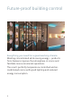
Future-proof building control Everything you need for a good working climate Working concentrated while saving energy – products from Siemens improve the atmosphere in rooms and facilitate more economical operations. The result: perfectly temperature-controlled and airconditioned rooms with good lighting and reduced energy consumption.
Highlights • Saves up to 30 percent energy with individual room control and energy saving functions • Protects investments on the basis of reliable products and the ability to add KNX devices • Easy commissioning and adaptation to changes in use due to tested applications • Extremely environmentally friendly due to energyindependent variants with EnOcean technology Contact and support GAMMA instabus: siemens.com/gamma Technical documentation: siemens.com/gamma-td HVAC Integrated Tool (HIT): siemens.
Application examples Backbone • and line couplers 8 • a KNX system Commissioning via Ethernet (LAN) 12 Commissioning • a KNX system via Ethernet (WLAN) 14 • Coupling KNX lines via Ethernet (LAN) 16 • access to a KNX system Remote via the Internet 18 KNX visualization via Ethernet (LAN) • 20 • properties with KNX Monitoring via Ethernet (LAN) 22 Using • DALI luminaires with easy KNX commissioning 24 • Presence- and daylight-dependent controls 26 6
• Constant light level control 27 • Sunlight tracking control 28 • Shadow tracking control 30 • Sunlight tracking control with shadow tracking control 31 • Wiring of lighting groups with DALI 32 • DALI topology with sensors 34 • Switching off standby with DALI 35 • Wireless remote control (KNX/EnOcean) 36 • Web-based visualization 38 • Integrating KNX into BACnet 40 7
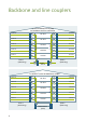
Backbone and line couplers N 140 line/backbone couplers 140 line/backbone couplers forNbackbone and line connection connection 2.5.0 for0 backbone and line 1.5. 1.5. 5th floor LK0 2LK .5.0 Line 1.4 Line 1.4 1.4.0 1.4. LK0 2.4.0 2LK .4.0 Line 2.4 Line 2.4 Line 1.3 Line 1.3 1.3.0 1.3. LK0 2.3.0 2LK .3.0 Line 2.3 Line 2.3 Line 1.2 Line 1.2 1.2.0 1.2. LK0 2.2.0 2LK .2.0 Line 2.2 Line 2.2 Line 1.1 Line 1.1 1.1.0 1.1. LK0 2.1.0 2LK .1.0 Line 2.1 Line 2.
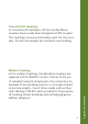
Modern topology In this modern topology, the backbone couplers are replaced with N 146/02 IP routers. Thanks to the use of standard network components, the connection for example of two building sections is no longer limited to bus line lengths. Use of other media such as fiberoptic cabling or WLAN is also possible for the purpose of coupling distant buildings and exchanging group address telegrams.
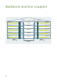
Line 1.2 1.2.0 Line 1.1 1.1.0 LK 3rd floor 2nd floor 2.3.0 Main line 2.0 1.3.0 Main line 1.0 Line 1.3 Line 2.3 LK 2.2.0 Backbone and line couplers LK LK 2.1.0 1st floor LK LK KNX Area 1 (West wing) 1.0.0 Data network (LAN) Line 2.2 Line 2.1 Area 2 (East wing) 2.0.0 N 146/02 IP router as backbone coupler Line 1.5 1.5.0 Line 1.4 1.4.0 Line 1.3 1.3.0 Line 1.2 1.2.0 Line 1.1 1.1.
Application examples Innovative topology In this innovative topology, all line couplers are replaced with N 146/02 IP routers. Backbone couplers are no longer needed. This configuration allows to connect every building floor by Ethernet (LAN) and utilize existing LAN networks. Moreover, correct configuration of the N 146/02 IP router enables major projects to be commissioned as smaller, individual subprojects in a simpler, clearer manner.
Commissioning a KNX system via Ethernet (LAN) KNX LAN (Ethernet crossover cable) IP interface LAN-enabled notebook KNX device KNX device KNX device In every GAMMA instabus project, the devices are commissioned after their installation. Once the physical addresses have been assigned, application programs, parameters and addresses are loaded to the devices. This can take some time in large-scope projects with many devices.
Benefits • Plan, configure, commission and diagnose with ETS, the KNX commissioning software • Simply connect your notebook and start the download • Downloading takes only half as long, thereby halving commissioning times and significantly reducing time at the project site Follow these steps • Connect the IP interface to the KNX bus line • Connect the notebook to the IP interface using the Ethernet crossover cable – and start the download 13 Application examples You will need • An IP interface N 148/22,
Commissioning a KNX system via Ethernet (WLAN) WLAN KNX LAN (Ethernet cable) IP interface KNX device WLAN router WLAN-enabled notebook KNX device KNX device In every GAMMA instabus project, the devices are commissioned after their installation. First, the physical addresses must be assigned. To do this, select the device in ETS on the notebook and press the programming key on the device.
Benefits • Wireless GAMMA instabus commissioning via WLAN • Possible to move freely throughout the building • Only one person needed for commissioning Follow these steps • Connect the IP interface with the KNX, and connect the WLAN router to the IP interface using the Ethernet cable – and you can go to each individual room with your notebook and the ETS • The related safety and security requirements governing the LAN and WLAN have to be observed 15 Application examples You will need • An IP interface N
Coupling KNX lines via Ethernet (LAN) KNX LAN (multicast-enabled) IP router KNX IP router KNX device KNX device KNX device The new KNXnet/IP standard enables KNX telegrams to be transmitted via Ethernet (LAN), which leads to new applications and solutions. Existing network infrastructure and technologies are used to transmit KNX data over longer distances. Connections between buildings or floors can be clearly and easily implemented with KNXnet/IP.
Benefits • LAN as the main and backbone line • Data can be transmitted over longer distances • Existing data network and components (LAN) can be used Follow these steps • Connect an IP router N 146/02 to every KNX line (instead of a line coupler N 140/03) • Connect the IP router N 146/02 via a multicastenabled LAN • Commission each IP router N 146/02 just like a “conventional” line/backbone coupler using ETS • Observe the related safety and security requirements governing the LAN 17 Application examples
Remote access to a KNX system via the Internet KNX LAN IP interface KNX device KNX device DSL router with VPN or ISDN/analog dial-up router Internet (via VPN connection or dial-up modem) DSL router or modem LAN KNX device In almost every project, changes are often requested during building completion or after the building goes into operation, for example if the set lighting times are too long.
Benefits • Parameters can be quickly changed by remote access • Remote access saves driving time and costs • Data security is ensured Follow these steps • Connect IP interface N 148/22 to the KNX and LAN • Configure the VPN DSL router or dial-up router 19 Application examples You will need • An IP interface N 148/22, for example • 24-V power supply for IP interface N 148/22, e.g. Power over Ethernet, unchoked bus voltage • VPN DSL router or ISDN/analog dial-up router • ETS; see knx.
KNX visualization via Ethernet (LAN) LAN-enabled PC with visualization KNX LAN (multicast-enabled) IP router KNX IP router KNX device KNX device KNX device When retrieving large numbers of data points cyclically for visualization in large projects, waiting periods can sometimes occur while data is being updated. Use your LAN as the main and backbone line and connect your PC for visualization to the LAN.
Benefits • LAN as the main and backbone line • Visualization up to 200 times faster than previously • High data volume possible • No data concentrators needed You will need • One IP router N 146/02 per line • IP Control Center N 152 • 24-V power supply for IP interface N 146/02, e.g. Power over Ethernet, unchoked bus voltage • Ethernet network (LAN) • ETS; see knx.
Monitoring properties with KNX via Ethernet (LAN) KNX KNX device KNX device IP interface Property 1 KNX IP interface Property 2 KNX device Internet VPN connection or intranet/LAN KNX IP interface Property 3 Some distributed properties need to be checked regularly for certain conditions and maintained accordingly, for example the fill levels of oil tanks in distributed apartment buildings or the operating hours of consumers. These states can now be reported centrally to any location.
Benefits • Central status messages for distributed properties • Less maintenance required • Optimization of maintenance costs You will need • One IP interface N 148/22 for each property, for example • 24-V power supply for IP interface N 148/22, e.g. Power over Ethernet, unchoked bus voltage • Visualization software • ETS; see knx.
Using DALI luminaires with easy KNX commissioning Switch/dimmer actuator or KNX/DALI gateway KNX DALI DALI-EVG DALI-EVG DALI-EVG DALI-EVG DALI-EVG DALI-EVG DALI-EVG DALI-EVG DALI-EVG DALI-EVG DALI-EVG DALI-EVG DALI-EVG DALI-EVG DALI-EVG DALI-EVG Up to 8 DALI ballasts per channel Ballasts with a DALI interface are used in lighting controls, e.g., to report lamp failure.
Benefits • True 0 to 100% light value control • High operating safety due to targeted shutdown in the event of an error • Error messages for luminaire groups • For individual room lighting control Follow these steps • Connect the switch/dimmer actuator N 525E to the KNX • Connect each group of DALI ballasts to be controlled jointly to one output of the switch/dimmer actuator N 525E • Configure each channel in ETS just as you would a conventional actuator and program the device 25 Application examples You
Presence- and daylightdependent control Channel 1: Lighting Channel 2: Sun protection Channel 3: HVAC The presence detector with integrated brightness control regulates up to three independent output channels for various functions in the room, such as lighting, sun protection and HVAC systems. The automation serves to optimally adjust the room temperature and brightness to the room’s actual use on a presence-dependent basis.
Constant light level control Daylight Artificial light Benefits • Integrated constant light level controller with main lighting group and up to four lighting subgroups with one brightness sensor • Automatic assignment of the artificial light distribution in the room to enable constant light level control of the up to five lighting groups via control characteristics • Entry of five brightness values, measured under the lights during pure daylight, as parameters in ETS • Automatic measurement of artificial
Sunlight tracking control 2 2 1 1 Total reflection 1 of direct sunshine 2 Portion from diffuse daylight With sunlight tracking control, the position of the sun is tracked so that the blind slats are not completely closed, but rather automatically adjusted to prevent the sun from shining directly into the room. The spacing between the blind slats still allows diffuse daylight to enter the room and contribute to ensuring glare-free room lighting while lowering electricity costs.
1 Weather station KNX DC 24 V 2 Power supply 3 Combi/sunblind actuator AC 230 V Drives M M 4 Shutter/blind switches for manual operation You will need • Weather station AP 257 • Electronic power supply unit • Sunblind actuator N 523/11 • Pushbutton, double UP 222/3 • Drives • Bus coupling unit UP 117/12 (for pushbuttons) 29 Application examples Benefits • Reduced energy consumption and costs for room lighting • Optimum room climate • Glare-free workplaces
Shadow tracking control 3 3 3 Maximum depth of sunlight penetration into the room With shadow tracking control, sun protection is not lowered completely but only so far that the sun can still shine into the room for a certain distance (e.g. 50 cm), which can be set by adjustable parameters. Benefits: This enables room occupants to look outside through the lower part of the window, and plants arranged on the windowsill can still be exposed to direct sunlight, while the room occupants are protected.
Sunlight tracking control with shadow tracking control 2 2 1 1 3 3 Total reflection 1 of direct sunshine 2 Portion from diffuse daylight Maximum depth of sunlight 3 penetration into the room You will need • Weather station AP 257 • Electronic power supply unit • Sunblind actuator N 523/11 • Pushbutton, double UP 222/3 • Drive • Bus coupling unit UP 117/12 (for pushbuttons) 31 Application examples The functions of sunlight tracking control and shadow tracking control can be performed with the sam
Wiring of lighting groups with DALI KNX DALI L1L2L3 DALI KNX AC 230 V 1 ... 10 V 1 ... 10V KNX L1L2L3 KNX 1 ... 10V KNX 1 ... 10V KNX 1 ... 10V KNX 1 ... 10V KNX 1 ... 10V KNX 1 ... 10V KNX 1 ...
Benefits • Lighting groups are not hardwire-connected • Possible to plan control lines and power supply separately • Even, uniform load distribution throughout the power supply network • Lower fire load thanks to fewer cables • Planning is simpler and faster • Integration of emergency lighting into the general lighting • Support for selected sensors with DALI interface • Switching off standby when lighting is turned off • Replacement of defective single-channel ballasts without software 33 Application exa
DALI topology with sensors KNX 10 more 6-mA sensors per channel KNX/DALI gateway DALI multisensor Sensor head (max. 8 PIR per channel) Channel A AC 230 V Channel B DALI Max. 190 mA per DALI channel Pushbutton DALI pushbutton interface 4-fold (max. 16 per channel) Max. 64 2-mA electronic ballasts per channel The KNX/DALI gateway can control up to 64 ballasts per channel. In addition, selected DALI sensors that meet specifications from Siemens can be commissioned together with the KNX/DALI gateway.
Switching off standby with DALI KNX DALI multisensor Sensor head (max. 8 PIR per channel) Switching actuator Channel A AC 230 V 10 more 6-mA sensors per channel KNX/DALI gateway Channel B DALI Max. 190 mA per DALI Channel Pushbutton DALI pushbutton interface 4-fold (max. 16 per channel) Luminaires with electronic ballasts usually need a closed-circuit current, even when the lighting system is turned off or is in standby mode.
Wireless remote control (KNX/EnOcean) KNX KNX device KNX device Wall transmitter AP 222 KNX/ EnOcean gateway Room operator units QAX9x.y KNX device In many indoor applications, cables are either not wanted, laying cables is too labor-intensive or simply not possible at all. Maintenance-free switches and room devices based on the open EnOcean communication standard are the ideal solution for these applications.
Benefits • Battery-free and thus environmentally friendly and maintenance-free • Communication via open standard • Mounting on any surface: glue or screw them in place, done • Can be upgraded without new cables • Can be connected to GAMMA instabus: KNX via KNX/EnOcean gateway You will need • KNX/EnOcean gateway RXZ97.1 • Further EnOcean devices, depending on the application • For lighting/sun protection applications: EnOcean wall transmitter AP 22x • HVAC applications: room operator units QAX9x.
Web-based visualization Web client smartphone Web client Web client tablet PC WLAN router ETS IP/Web KNX Web server + KNXnet/IP interface Motion Room Switching Weather Central detection temperature station operation Dimming Blinds control Touch panel Pushbutton The Control Center N 152 is a compact visualization controller.
Benefits • IP Control Center N 152 • An integrated Web editor • For all Web-enabled operating devices such as PCs, notebooks, tablets and smartphones • Create customized visualization of operating and display interfaces Follow these steps • Connect the IP Control Center N 152 to the KNX, and configure and program it in ETS • Create the visualization of the operating and display interfaces via the Web editor • The related safety and security requirements governing the WLAN shall be observed 39 Application
Integrating KNX into BACnet Legend: 3 1 KNX installation 2 IP gateway KNX/ BACnet N 143 2 1 Individual room 2 2 3 BACnet-based building automation system 1 1 School Office building The IP gateway KNX/BACnet enables KNX installations to be integrated into BACnet-based networks and building automation systems quickly, simply and efficiently. No separate commissioning interface is needed owing to the KNXnet/IP interface integrated into the gateway.
Benefits • Commissioning of the IP gateway KNX/BACnet N 143 by the KNX installation technician only using the ETS • Integration of a KNX installation into a BACnet system without KNX knowledge by the BACnet system integrator • Clear separation of responsibility for KNX installation and BACnet system integration/building management • Simple, flexible integration of a KNX installation • Integrated Web server for documentation of the configuration and export of an EDE file • Configuration of a KNX installation
Glossary Definitions and explanations of certain technical terms used in the previous chapters 43
AC Alternating current ASCII ASCII (American Standard Code for Infor mation Interchange) is a 7-bit character encoding standard that enables data exchange. ASHRAE ASHRAE (American Society of Heating, Refrigerating and Air-Conditioning Engineers) is a globally active American association for engineers focusing on technical building services. BTL The BTL brand was developed by the American BACnet International for BACnet Testing Laboratories (BTL).
Designates the good agreement of something with the codes and standards governing that particular context DALI DALI (Digital Addressable Lighting Interface) is a digital interface that is integrated into the ballasts of luminaires and permits flexible wiring and commissioning. In addition to switching and dimming functions, it also detects and transmits lamp failures. DC Direct current DIN DIN stands for Deutsches Institut für Normung e.V., the German Institute for Standardization.
EnOcean The EnOcean Alliance was formed by leading companies in the building automation industry with the goal of implementing innovative wireless solutions for sustainable building automation projects. ETS The ETS (Engineering Tool Software) is a vendor-independent commissioning software for all KNX devices. Group Communication between KNX devices address (KNX) is performed via group addresses. They contain a clear function or piece of information.
The ISO (International Organization for Standardization) is the international association of standardization organizations. KNX Association The KNX Association is an amalgamation of over 400 companies in 35 countries who have agreed on a standard technol ogy known as KNX for exchanging telegrams between sensors and actuators within building automation systems. The Engineering Tool Software (ETS) is a vendor-independent commissioning software for KNX devices.
LAN LAN is the abbreviation for Local Area Network. Data transfer on LANs is organized by IP (Internet Protocol) – the standard network protocol on the Internet. LON/ LonWorks A LON (Local Operating Network) is a decentralized network. LonWorks Network Services also provides services for installation, administration, analysis and license controlling of LON networks. Object Term denoting an example of a particular data type. Every object is characterized by state, behavior and identity.
PL PL (Power Line) is a connection via the AC 230 V power supply grid. PoE PoE (Power-over-Ethernet) refers to a method for supplying power to networkable devices over the 8-wire Ethernet cable. Protocol A system of rules that specify the format, content, meaning and order of messages transmitted between various entities of the same communications system RTU Remote terminal unit SELV Safety extra-low voltage TCP The TCP (Transmission Control Protocol) is part of the TCP/IP protocol family.
UDP Besides TCP, the UDP (User Datagram Protocol) is the most important transport protocol of the Internet protocol family. As a minimal, connectionless network protocol, it is also used in the BACnet/IP standard, and forms there the basis for efficient processing of the actual data traffic. VDE VDE is the Verband der Elektrotechnik Elektronik Informationstechnik e.V., the German Association for Electrical, Electronic & Information Technologies.
An interface based on Web technologies for exchanging data between computers on the Internet (machine-to-machine communication) WLAN Wireless Local Area Network, i.e.
Published by Siemens Switzerland Ltd 2018 Building Technologies Division International Headquarters Gubelstrasse 22 6301 Zug Switzerland Tel +41 41 724 24 24 Subject to changes and errors. The information given in this document only contains general descriptions and/or performance features which may not always specifically reflect those described, or which may undergo modification in the course of further development of the products.