Manual LMSmodular Applications Section 6 Cerberus® LMSmodular Foreign Host Interface FHI Pad Ver.
Data and design subject to change without notice. / Supply subject to availability. © Copyright by Siemens Building Technologies AG We reserve all rights in this document and in the subject thereof.
1 1.1 1.2 1.3 2 2.1 2.2 2.3 2.3.1 2.3.2 2.4 2.4.1 2.4.2 2.4.3 2.4.4 3 3.1 3.2 3.2.1 3.2.2 3.2.3 3.2.4 3.2.5 3.2.6 3.2.7 3.2.8 3.3 3.4 3.5 4 4.1 4.2 4.2.1 4.3 4.4 4.5 4.6 5 6 6.1 6.2 7 8 9 10 Introduction .................................................................................. 1 Who will use this manual .................................................................. 1 Related documents.......................................................................... 1 Document description .............
1 Introduction 1.1 Who will use this manual The FHI Pad - Engineering Guidelines document is addressed to Cerberus technical supervisors who will manage an installation that includes an FHI Pad. The FHI Pad permits integration between the Cerberus LMS supervising system and a Foreign Supervision System (FSS) handling technological plant management. This document is designed to assist technical personnel acquire a full understanding of system capabilities and performance.
The Appendices (from A to C) have been inserted for reference and contain some templates to be used during integrated system engineering. For CS11, CS4, CS4-40 and CC60 please refer to description table on LMSmodular. Appendix A and B supply you with forms to represent the security points inside FSS (Appendix A) and to represent technological points as cluster of (virtual) CMX units inside LMS (Appendix B). Eventually, Appendix C gives you a form to define interactions between FSS and LMS devices.
2 Basic concepts of integrated system 2.1 System architecture FHI Pad is an interface that allows the Cerberus danger management System to transfer real time information regarding its status to a supervision system other than Cerberus' LMS, named in this document Foreign Supervision System (short FSS). The FHI Pad interface allows the Cerberus danger management system to receive commands from a Foreign Supervision System.
tion, the control panel will transmit a message to the management station that reflects the status of the device. Up to 16 different states are available for each security/safety device. The messages coming from up to 16 control panel are collected by a dedicated front-end processor, the Gateway GW-20. This microprocessor-based device polls the control panels and communicates with the PC-based management station.
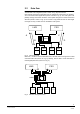
2.2 Data flow The data flow in the integrated system is shown in Fig. 3 by black arrows. LMS controls and receives information from the subsystems connected to the gateway, as in normal stand alone applications (arrows A and B in Fig. 3). The FSS system can partially manage and monitor Cerberus control panel through the FHI Pad connection with FSS (arrows C and D in Fig. 3). The control is only partial because the exchanged messages are only a subset of those available to LMS system.
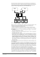
Interactions between Cerberus subsystems and FSS field devices are allowed by the FHI Pad connection and by the communication between Subsystem Pads and FHI Pad on the gateway bus. These interactions are automatically triggered by an event or a sequence of events arising in LMS systems (arrow marked E in Fig. 5. LMS FSS E GW20 CZ10 CS11 CZ12 CS4 Fig.
control panel. This operation, that cancels pending alarms is a very sensitive one and must be performed by specially trained personnel. 2.3 Data representation Each physical device connected to the Cerberus or FSS control panel has a finite set of states. These states, such as normal operation, alarm, fault and so on, are modeled and internally reproduced by the monitoring software. 2.3.1 Security points The way LMS manages the security events is based on the use of a number of tables.
Five types of events can be configured: SEVERE ALARM ALARM FAULT WARNING ANOMALY A further table, called the Description Table specifies how the message is to be displayed on the monitor screen. User operation (such as alarm acknowledge and reset) or field events (e.g. automatic or manual control panel reset) can change the points' state. In this case the new point value is displayed accordingly to the description and treatment tables as configured.
2.4 Limits The implementation of technological plant control on LMS and of security system on FSS has some limits. These limits can be divided into two categories: § design limits. Some controls, functions or data that are available in one of the two systems (FSS or LMS) are not transferred by the FHI Pad to the other. This means that the technological system seen by LMS is only a subset of the system as seen by FSS. The same applies to security system seen by FSS. § configuration limits.
2.4.4 Security/safety points supported by FSS A subset of the security/safety points (from a CZ10, CZ12 or CS4) is supported by the FSS. Other peripheral devices supported by LMS as a stand-alone system (refer to LMS documentation for a complete list) cannot be managed by the FSS. Only a subset of telegrams and commands exchanged between the CZ10/CZ12 control panel and the gateway is managed by the FSS.
CZ12/CS4 (Pad V5.20) Gateway_link_status General_fault Power_fault Fault_xmit Intrusion_alarm_tx Line_sabotage Panel_sabotage Organization Part_off Addresses [zones] Groups [sections] Duress_alarm Time_program Address_lock [zones] POINT DESCRIPTION CS4 version 6a (Pad V5.25) POINT DESCRIPTION Addresses [zones] Address_lock [zones] CS4 version 7 (Pad V5.25) POINT DESCRIPTION Addresses [zones] Group [section] Time program Address_lock [zones] CS4-40 version 6a and 7 (Pad V5.
CC-11 SUPPORTED COMMANDS Status request General reset General acknowledge Section acknowledge Section reset Exclude all zones of a section Include all zones of a section Night switch over Day switch over Control element on Control element off Exclude zone Include zone CZ12 / CS4 /CS4-40 Status request Reset Acknowledgement Night switch over Day switch over Include group / section Exclude group / section SUPPORTED COMMANDS CC60 SUPPORTED COMMANDS Status request Reset Acknowledgement Night switch over Day s
3 Security control panel points managed by FSS 3.1 Supported devices The FHI Pad only supports the following Cerberus control panels: CZ10 (fire and technological sub-sector) CS11 CZ12 CS4 CS4-40 CC60 Only the most meaningful subset of telegrams and commands of these subsystems is supported, as specified in the following paragraphs. The security and safety subsystems listed above communicate with the gateway using the Cerban Protocol.
3.2.1 CZ10 points representation The following table presents the CZ10 image in terms of FSS blocks and the specific values representing the different states. Point number 1 Point description Gateway_link_status 3 General_fault 5 Power_fault 6 Fault_xmit 7 Fire_alarm_xmit 8 Fire_alarm 10 Fire_organization 11 Fire_part_off 16-111 Fire\Tech_group 264-1463 Line_elements 168-263 Technical_digital_outputs Status normal fault net fault normal fault normal fault battery off on off on normal
3.2.2 CZ10 supported commands The following table presents all CZ10 commands available to an FSS user. Commands do not require any configuration on FSS.
Cerban or Cerloop CK11 810 CC11 111 CC11 112 C-Bus CC11 113 CC11 114 Fig. 8 1 2 3 4 5 6 7 8 9 10 11 12 13 Fig. 9 Message Format Each box is a byte and all data are ASCII characters.
CC-11 points representation The version 5.20 supports the following structure numbers (EP2/A) with the related messages: Structure number Point description Status Block value Treatment flag Gateway link status normal fault partdiscon normal fault normal fault battery normal fault alarm inactive active inactive active normal gen.al night day normal excluded warning test alarm auto not ready alarm man.
The pad version 5.
The pad version 5.
3.2.4 CS-11 supported commands The following table presents all CS11 commands available to an FSS user. Commands do not require any configuration on the FSS.
According to the LMS organisation, the CZ12, CS4 and CS4-40 are managed with the following subsystem subtype: § 0 CZ12 with Cerban protocol (decimal, 96 zones) § 1 CZ12 V5 with Cerban protocol (decimal, 96 lock zones) § 2 CS4 V6 with Cerban protocol (decimal, 50 users) § 3 CS4 V6a and v7 with Cerban/hex protocol (hexadecimal, 128 zones and lock zones) § 4 CS4-40 V6a with Cerban/hex protocol (hexadecimal, 254 zones, lock zones, masking zones) § 5 CS4-40 V7 and V8 with Cerban/hex protocol (hexadecimal, 512 zo
For CS4 version 6a , the pad version 5.25 supports the subtypes 3 and the following points with the related messages: Point number 358-389 #128 Point description Addresses [zones] 390-421 #128 Address [zone] lock Status normal excluded test no ready sabotage al. + sab. testalarm alarm normal on Block value 5 4 3 2 0 1 6 7 5 4 Treatment flag 0 1 1 2 2 2 2 2 0 1 For CS4 version 7, the pad version 5.
In order to discriminate the range for the Zones, the following rule applies to the two identification data block field (1 and 2): Identification data block 0401-04FA 0501-05FA 0601-06FA 0701-07FA Zona range 1-250 251-500 501-750 751-1000 Identification data block 0801-08FA 0901-09FA 0A01-0AFA 0B01-0BFA Zona range 1-250 251-500 501-750 751-1000 Identification data block 0C01-0CFA 0D01-0DFA 0E01-0EFA 0F01-0FFA Zona range 1-250 251-500 501-750 751-1000 The ranges are defined up to 1000 zones (although t
Command parameter It is an optional command parameter. This parameter is the block corresponding the group number to be included/excluded for command no. 24 and 25. (*) This general command requires (as parameter) one of the block numbers (any) which belongs to the control unit. At FSS level you must not use an automatic acknowledge command because this forbids the remote transmission alarm on CZ12, CS4 and CS4-40, a condition that could be potentially dangerous. 3.2.
3.2.8 CC60 supported commands The following table presents all the CC60 commands available: Command description Status request Reset * Acknowledge Night switch over Day switch over Include gas detector Exclude gas detector Technical output on Technical output off Command number 0 2 1 6 7 27 26 30 31 Command parameter block # block # (*) block # block # block # block # block # block # block # (*) Before version 5.25 the Reset command is available only for the FHI pad, since version 5.
3.5 Security/safety commands treatment.
4 Technological control panel points managed by LMS 4.1 Supported technological plant item The integrated systems support any technological plant item that complies with the FSS requirements and communicates with FHI Pad using the Cerberus Dati Standard Protocol. 4.2 LMS technological point modeling The LMS workstation accesses a subset of the data points configured in the FSS system through the FHI Pad interface.
The first unit in the cluster must be reserved for diagnostic puposes. CMX # 2 - 32, local address 01H - 1FH, subtype 4,5,7 # Point 01 02 03 04 05 06 07 .. 27 Description Link status with FSS Subsystem scan status Not used 1st digital input/output 2nd digital input/output 3rd digital input/output 4th digital input/output ........................ 24th digital input/output Points 1-3 of unit 1 are used for general diagnostics information.
4.3 Analog points The analog point representation will be implemented in future versions of LMSmodular. 4.4 Command representation The following table presents the list of CMX commands (telegram description and meaning) supported by the FHI Pad. Commands are transmitted to the FHI Pad in CDSF. Command number. 00 00 01 02 03 04 05 06 07 08 09 10 11 12 13 14 15 16 17 I/O type 0 0 Address number add add Par. 01 0 1 Par. 02 0 val0 Par. 03 0 val1 Par. 04 0 val2 Par. 05 0 0 Done Ope.
4.5 FHI Pad Technological points image FHI Pad maintains an image of all technological points to be transmitted to the LMS using a technological point table. This table contains the correlation between the FSS block representation and the CMX points that represent technological points inside LMS. When a change of status occurs in the technological field devices, the FSS issues a Standard Protocol message to the FHI Pad.
5 Special commands from FSS The FSS can set the date and time on the FHI Pad using the special command 0,1. The structure of this command is shown in the table below.
7 Configuration notes The FHI Pad deals with a subset of blocks configured on the FSS system. NISE_CNF is the software tool used to configure FHI Pad board EPROMs.
8 Appendix A - Security points table LMS Control panel Type: Subsystem Pad Number: Control panel Local Address Control panel Subtype: Serial line Number N. Point Number 1 2 3 4 5 6 7 8 9 10 12 13 14 15 16 17 18 19 20 21 22 23 24 25 26 27 28 29 30 Point Description Control Panel Type Subsystem Pad number Control Panel local address Control Panel Subtype Serial Line number Point number Point Description Point Type Block number FSS Point Type Block num.
9 Appendix B - Technological points table LMS INFORMATION : : : Local address (cluster) CMX Subtype Subsystem description N.
10 Appendix C - Interaction table INTERACTIONS System : Gateway # : Subsystem/FHI Pad - Slot # : SOURCE SUBSYSTEM Row# Description Number Type 1 2 3 4 5 6 7 8 9 10 12 13 14 15 16 17 18 19 20 21 22 23 24 System Gateway # Subsystem/FHI Pad - Slot # Row# Interaction Program # Target subsystem Description Source Event Interaction Program # REACTIONS : : : Comments: Command # Type 1 2 3 4 5 6 7 Row# Interaction Program # Target subsystem Description Comments: Command # Type 1 2 3 4 5 6 7 Each row c
36 Siemens Building Technologies Cerberus Division e1143b 06.
Keyword index C CC60 I, 2, 3, 11, 12, 13, 25, 26, 27, 34 CDDL 1, 2, 4 CDDL Cerberus Dati Data Link 1 CDSF 1, 2, 4, 28, 30, 31 CK 11 Gateway 16 CS11 2, 3, 9, 13, 16, 21, 27, 34 CS4 I, 2, 3, 9, 10, 11, 12, 13, 21, 22, 23, 24, 25, 34 CZ10 I, 3, 9, 10, 11, 13, 15, 16, 27, 32, 34 CZ12 I, 3, 9, 10, 11, 12, 13, 21, 22, 23, 24, 25, 27, 34 F FHI Pad 1, 3, 4, 5, 6, 8, 9, 13, 26, 28, 29, 30, 31, 32, 33, 36 FSS I, 2, 3, 4, 5, 6, 7, 8, 9, 10, 13, 15, 16, 17, 21, 24, 25, 26, 27, 28, 29, 30, 31, 32, 33, 34, 35 1 Siemen
Siemens Building Technologies AG Cerberus Division CH-8708 Männedorf Alte Landstrasse 411 Tel. +41 1 - 922 61 11 Fax +41 1 - 922 64 50 www.cerberus.ch Siemens Building Technologies Cerberus Division Cerberus Security for People and Assets Replaces e1143a Doc.no Edition: e1143b 06.