GAMMA instabus OEM- Product Catalogue Release: February 2012 KNX EIB TP-UART 2-IC Features • • • • • • • • • • • • • • Signaling for standard UART (LSBFirst, Idle is 1) Baud rate 9600 or 19200 for the communication: TP-UART 2 Host – Controller Direct coupling to host controller (TxD, RxD), or via optical couplers (optional) 2-wire protocol with software handshake Buffering of sent frames No critical timing during transmission VCC switchable between 3.
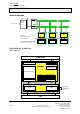
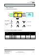
GAMMA instabus Release: February 2012 KNX EIB TP-UART 2-IC GENERAL DRAWING A - Bus + P o w er S u pp ly 2 30V / 5 0H z 3 0V B - Bu s - TP -UA RT IC O ptio nal Electrica l Isolation RxD TxD TP -UA RT IC RxD TP -U A RT IC TxD Rx D TxD (O pto co uple r) A pplication ...
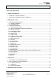
GAMMA instabus Release: February 2012 KNX EIB TP-UART 2-IC TABLE OF CONTENTS 1 MODES OF OPERATION .......................................................................................................................5 1.1 INTERFACE TO HOST ELECTRONICS........................................................................................................... 5 1.2 SELECTION OF DIFFERENT MODES OF OPERATION.................................................................................
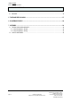
GAMMA instabus Release: February 2012 KNX EIB TP-UART 2-IC 4.1 PACKAGE....................................................................................................................................................... 34 5 TAPE AND REEL PACKING.................................................................................................................37 6 SOLDERING PROFILE .........................................................................................................................
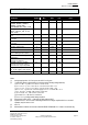
GAMMA instabus Release: February 2012 KNX EIB TP-UART 2-IC 1 1.1 Modes of Operation Interface to host electronics TP - UART - IC Analog Digital Part Part EIB TxD RxD HOST Controller TxD3 RxD3 Normal Mode: IDLE = HIGH Bus Coupler IDLE = HIGH Mode: IDLE = LOW IDLE = LOW 1.2 Selection of Different Modes of Operation Mode of operation MODE 0 1 2 TEST MODE CTM TSTIN_BDS TSTOUT_TW 3 Normal 1 1 0 0 0 0 Analog 1 0 0 0 0 0 BDS=0: 19.2 kBd at UART BDS=1: 9.
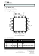
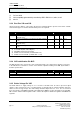
GAMMA instabus Release: February 2012 KNX EIB TP-UART 2-IC 2 The ANALOG – PART 2.1 Package and Pin Definitions 2.1.
GAMMA instabus Release: February 2012 KNX EIB TP-UART 2-IC 6 VDDH 7 SVCC 8 VCC AIO AIO AIO 9 IND AIO 10 VB- S 11 VB+ S 12 13 14 15 16 BYP TXO STxO RxIN VB- 17 VIF 18 SAVE 19 RESn 20 RxD 21 22 23 24 25 26 27 28 X1 X2 V20PD NC2 NC3 VDP 29 TSTIN_BDS DIO DI DI DI DI DI DI DI VDP VDP VDP VDP VDP VDP VDP DIV CTM_AMS MODE 3 MODE 2 MODE 1 MODE 0 TESTMODE PIN Types: SMPS control VCC control External power supply 3.
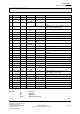
GAMMA instabus Release: February 2012 KNX EIB TP-UART 2-IC DI_PD DIO_PU DO DO_PU NC 2.2 ... ... ... ... ... digital input with pull down digital I/O with pull up digital output digital output with pull up Not connected. Recommend to be tied to VB in the application. OPERATING CONDITIONS 2.2.1 General operating conditions All specification parameters, unless otherwise stated, are valid within the General operating conditions. Unless otherwise stated all voltages are referenced to the VB- pin.
GAMMA instabus Release: February 2012 KNX EIB TP-UART 2-IC Parameter Symbol Min Max Unit voltage on pin IND VIND -0.3 50 V voltage on low voltage pins MODE0, MODE1, MODE2, MODE3, TSTIN_BDS, TESTMODE, DIV, SVCC, CTM voltage on low voltage pins TxD, RESn, TSTOUT_TW, X1, X2, RxD, SAVE Internal supply voltage to digital part voltage used for internal DC/DCconverter voltage used for internal DC/DCconverter Ambient temperature VLV1 -0.3 VDP +0.5 V 9) VLV2 -0.3 VIF +0.5 V 5) VVDP -0.
GAMMA instabus Release: February 2012 KNX EIB TP-UART 2-IC (7) (8) (9) For Rth ≤ 28k/W Valid susceptibility against humidity is described by JEDEC JESD22 A112, table 1, level 5 Max. 5V 2.2.3 Bus Pins VB+ and VBVia these pins the ASIC is connected to the bus lines. External diode to prevent reverse bias of ASIC and external suppressor diode to limit the burst pulses are required. Symbol VVB+ Ianalog Inormal Ianalog Inormal 1) 2) 3) 4) 5) Parameter Min Max Unit Note positive line voltage -0.
GAMMA instabus Release: February 2012 KNX EIB TP-UART 2-IC Symbol VVSP VVDIF CVSP ESRVSP1 Parameter Min Max Unit Note energy buffer voltage VVB+ - VVDIF 45 V 1) voltage difference between VVB+ and VVSP 0.5 2 V external storage capacitance 264 µF 2) 6) ESR of external storage capacitance evaluated @ 0.70 120Hz ESRVSP2 ESR of external storage capacitance evaluated @ 0.20 100kz 1) DC voltage of bus is 20V to 30V.
GAMMA instabus Release: February 2012 KNX EIB TP-UART 2-IC Symbol VIN VVCC[5] VVCC[3] CVCC LVCC LVCC Parameter input voltage supply voltage (generated by the ASIC) supply voltage (generated by the ASIC) external storage capacitance External Inductance External Inductor CVCCESR IVCC 1) 2) 3) 4) Min 6.25 5.0-5% 3.3-5% 8 Max 33 5.0+5% 3.3+5% 18 220 Series loss resistance ≤ 7.5 0.3 0.
GAMMA instabus Release: February 2012 KNX EIB TP-UART 2-IC 2.2.9 Supply Pin V20 and Pin R20 Pin V20 delivers the internally generated supply voltage to external loads. The supply is generated by a series regulator. Internal input voltage for V20 is VDDH. The V20 regulator is switched off during softstart, making V20 unavailable An external short-circuit from the V20 pin to VB- will not cause a destruction of the ASIC, interference on the bus or disturb generation of VCC.
GAMMA instabus Release: February 2012 IV20 [mA] KNX EIB TP-UART 2-IC Figure 3 V20 Fallback Characteristic 2.2.10 Pin IND, SMPS-output The pin IND is the output of the switched mode power supply. Internally the node is clamped to VB-. The voltages and currents depend on the switched mode power supply concept. 2.2.11 Pin SVCC This input pin controls the value of VCC. It is possible to switch between 3.3 V and 5 V. If pin SVCC is connected to VB-, VCC-voltage is 3.3 V.
GAMMA instabus Release: February 2012 KNX EIB TP-UART 2-IC 2.2.13 Transmit Pin TxO The transmit pin is connected to VB+ via external resistor of typ. 68 Ω. Symbol Parameter dVBUS delta(VBUS) during active LOW pulse 1) related to VB+ Table 14 Transmit Pin TxO Min -6 Max -9 Unit Note V 1) 2.2.14 Supply Pin VIF The Pin VIF is used as supply voltage for the pins TxD, RxD, RESn, SAVE, TSTOUT_TW, X1, X2 and determines their high input or output level.
GAMMA instabus Release: February 2012 KNX EIB TP-UART 2-IC Symbol Parameter Min VIL voltage range for input low level VIH voltage range for input high level 0.7 * VIF Vhyst hysteresis for switching level 0.1 * VIF RPullDown value of internal pull-down resistor 150 1) switching level approx. VIF/2, i.e. VIF/2 ± Vhyst/2 Table 17 Interface Pin RxD Max 0.3 * VIF 0.4 * VIF 450 Unit Note 1) kΩ 2.2.17 Interface Pin TxD The UART interface output pin TxD transmits the information to host electronic.
GAMMA instabus Release: February 2012 KNX EIB TP-UART 2-IC 2.2.19 Reset Pin RESn This pin is an I/O pin with internal pullup resistor to VIF. In reset case the reset pin delivers an active LOW signal to external host electronic. The output driver is realized as open drain. The reset state RESn = LOW can be caused by an internal or by an external RESET due to forcing an active LOW to the pin RESn. The switching levels are derived from external supply VIF.
GAMMA instabus Release: February 2012 KNX EIB TP-UART 2-IC 2.2.22 Pin TSTOUT_TW TW = HIGH means: chip temperature is higher than maximum allowed value and TxO is disabled. Symbol VOH VOL tr, tf Parameter Min Output HIGH voltage VIF - 0.5 Output LOW voltage rise time, fall time (10 % ↔ 90 %) Table 23 Pin TSTOUT_TW Max Unit V V ns 0.4 100 Note IOH = -5 mA IOL = 5 mA CL = 150 pF 2.2.23 Pin SAVE This pin is an open drain output with internal pull-up resistor to VIF.
GAMMA instabus Release: February 2012 KNX EIB TP-UART 2-IC 3 Digitalpart TP-UART 2 is at the digital interface compatible with TP-UART. This means that the same drivers and stacks can be used without modification. In addition TP-UART 2 supports some additional useful services. These services reduce the necessary performance in the microcontroller. 3.
GAMMA instabus Release: February 2012 KNX EIB TP-UART 2-IC 3.2 UART – Interface to host controller 3.2.1 Configuration and Timing The TP-UART-IC has a full duplex UART-interface to transmit and receive KNX frames asynchronously. The baud-rate depends on the setting of BDS pin (9600 or 19200).
GAMMA instabus Release: February 2012 KNX EIB TP-UART 2-IC U_ActivateBusyMode U_ResetBusyMode U_MxRstCnt + Repetitions U_ActivateCRC U_Set_Address +PhysAddressHigh +PhysAddressLow U_L-Data Start + CTRL-Byte U_L-Data Continue (index) + Data-Byte U_L-Data-End + Checksum U_PollingState (Slotnumber) + PollAddrHigh + PollAddrlow + State • • • • • • • • • Uart-Control Field 7 6 5 4 3 2 1 0 Servicename Hex 0 0 0 0 0 0 0 0 0 0 0 0 0 0 0 1 0 0 0 0 0 0 1 n 0 1 0 b 1 0 1 a U_Reset.request U_State.
GAMMA instabus Release: February 2012 KNX EIB TP-UART 2-IC 3.2.3.1.2 U_State.request-Service Requests the internal communication state from the TP-UART-IC. The TP-UART-IC answers with the Communicationstate. UART-Controlfield (02hex) 7 6 5 4 3 2 1 0 0 0 0 0 0 0 1 0 Fig. 5: U_State.request-Service 3.2.3.1.3 U_ActivateBusmon-Service Activates the busmonitormode.
GAMMA instabus Release: February 2012 KNX EIB TP-UART 2-IC 3.2.3.1.6 U_ResetBusyMode The service U_ResetBusyMode deactivates immediately the BUSY mode in the TP-UART. All addressed telegrams are answered according to the intern address flags. The host shall synchronize its receiver before sending the U_ResetBusyMode. UART-Controlfield (22hex) 7 6 5 4 3 2 1 0 0 0 1 0 0 1 Fig. 9: U_ResetBusyMode 3.2.3.1.7 0 0 U_SetAddress This service configures the physical address of the TP-UART.
GAMMA instabus Release: February 2012 KNX EIB TP-UART 2-IC - Frameformat Extended: Octet 0 Ctrlbyte 00R1cc00 Octet 1 extCtrlbyte Axxx xxxx Octet 4 High byte destaddress Octet 5 Low byte destaddress ... ...
GAMMA instabus Release: February 2012 KNX EIB TP-UART 2-IC Interchargap (2Bit) Receive from Bus 67ps Send to Controller ps Parity 1 Startbit Addresstype s 01234567ps s 01234567ps 1 Stopbit TPCI s 01234567ps Addresstype s 01234567ps 8 Datenbits 15 Bit Pause Checksum s 01234567ps TPCI s 01234567ps Ack s 01234567ps Checksum s 01234567ps Ack-Information s 01234567ps Rec from Controller Send to Bus s 01234567ps Time for Addresssearch (17 Bit) 1 Bit Buffertime 1 Bit Buffertime Fig.
GAMMA instabus Release: February 2012 KNX EIB TP-UART 2-IC 3.2.3.1.9 U_L_Data-Services The U_L_Data-Services are used to transfer the complete EIB-Linklayer-Frame (L_Data.request and L_PollData.request) to the TP-UART. If the host sends a second frame (the first frame buffer is yet active) the TP-UART rejects this and reports it with a Status.indication (PE bit set). HOST EIB U_LDATA_Start U_LDATA_Cont(1) U_LDATA_Cont(2) . . . U_LDATA_End Ctrl-Byte Ctrl-Byte 1. Databyte 1. Databyte 2.
GAMMA instabus Release: February 2012 KNX EIB TP-UART 2-IC EIB HOST Ctrl-Byte Ctrl-Byte 1. Databyte 1. Databyte 2. Databyte 2. Databyte immediate Ack-Info . . . . TP-UART Chksum Chksum immediate Ack Fig. 15: TP-UART receive telegram 3.2.3.1.9.1 U_L_DataStart-Service The U_L_DataStart-Service initialize the TP-UART-IC to receive a complete EIB-Linklayer-Frame from the host.
GAMMA instabus Release: February 2012 KNX EIB TP-UART 2-IC control field data link frame type FFR1 cc00 FFR1 0000 L_DATA request FFR1 1000 L_DATA request FFR1 0100 L_DATA request FFR1 1100 L_DATA request 1111 0000 L_POLLDATA request Fig. 17: Legal EIB-Controlfield 3.2.3.1.9.
GAMMA instabus Release: February 2012 KNX EIB TP-UART 2-IC The TP-UART calculates over the complete received telegram (including the Layer 2 checksum) a CRC16-CCITT with the following parameters: - Width= 16 bit - Truncated polynomial = 1021hex - init value = FFFFh - I/O not reflected - no xor on output CRC - Test string „123456789“ is 0xE5CC and adds it to the receiving frame (sending order is highbyte then lowbyte). After Reset CRC calculation is disabled.
GAMMA instabus Release: February 2012 KNX EIB TP-UART 2-IC PollAddr s 0 1 2 3 4 5 6 7 p s Receive from Bus Slotcount s 0 1 2 3 4 5 6 7 p s Checksum s 0 1 2 3 4 5 6 7 p s Slot 0 s 0 1 2 3 4 5 6 7 p s s 0 1 2 Send to Controller PollAddr s 0 1 2 3 4 5 6 7 p s Rec From Controller Pollingstate s 0 1 2 3 4 5 6 7 p s Slot 0 s 0 1 2 3 4 5 6 7 p s Send to Bus Fig.
GAMMA instabus Release: February 2012 KNX EIB TP-UART 2-IC repeat flag = 0: repeated L_DATA frame repeat flag = 1: not repeated c1 c0 0 0 system priority 1 0 urgent priority 0 1 normal priority 1 1 low priority class class repeat flag Control Field 7 6 5 4 3 2 1 0 Layer-2 Services 1 0 r 1 c1 c0 0 0 L_DATA.req 0 0 r 1 c1 c0 0 0 L_EXT_DATA.req 1 1 1 1 0 0 0 0 L_POLLDATA.
GAMMA instabus Release: February 2012 KNX EIB TP-UART 2-IC Each L_Data-request is transmitted completely to the Host. From a L_PollData-request only the Controlbyte is transmitted to the host if the TP-UART is a polling slave. If the TP-UART is polling master the complete polling frame is transmitted to the host as well if a collision is detected during sending the polling master frame.
GAMMA instabus Release: February 2012 KNX EIB TP-UART 2-IC 3.2.3.1.12.1 TP-UART-Reset.indication Service The Reset.indication service is sent after each reset if 40 bit-times line idle was detected. TP-UART-Controlfield 7 6 5 4 3 2 1 0 0 0 0 0 0 1 Fig. 29: TP-UART-Reset.indication-Service 3.2.3.1.12.2 0 1 TP-UART-ProductID.response Service The ProductIdentifier.response service is sent if a U_ProductID.request service was received from the host.
GAMMA instabus Release: February 2012 KNX EIB TP-UART 2-IC 4 4.1 Mechanical Specification Package Package type: Punched QFN36 6x6x0.9mm Figure 4 Package outline, Punched QFN 6x6x0.9mm 36LD 0.5mm Lead Pitch Technical Manual page 34 pages 42 © Siemens AG 2012 Subject to change without further notice. Siemens AG Infrastructure and Cities Sector, Building Technologies Control Products and Systems P. O.
GAMMA instabus Release: February 2012 KNX EIB TP-UART 2-IC Figure 5 Package dimensions, Punched QFN 6x6x0.9mm 36LD 0.5mm Lead Pitch (Variant C) Siemens AG Infrastructure and Cities Sector, Building Technologies Control Products and Systems P. O. Box 10 09 53, D-93009 Regensburg pages 42 © Siemens AG 2012 Subject to change without further notice.
GAMMA instabus Release: February 2012 KNX EIB TP-UART 2-IC Figure 6 Package notes, Punched QFN 6x6x0.9mm 36LD 0.5mm Lead Pitch Technical Manual page 36 pages 42 © Siemens AG 2012 Subject to change without further notice. Siemens AG Infrastructure and Cities Sector, Building Technologies Control Products and Systems P. O.
GAMMA instabus Release: February 2012 KNX EIB TP-UART 2-IC 5 Tape and Reel Packing Figure 7 Tape and Reel Packing 1 Figure 8 Tape and Reel Packing 2 Siemens AG Infrastructure and Cities Sector, Building Technologies Control Products and Systems P. O. Box 10 09 53, D-93009 Regensburg pages 42 © Siemens AG 2012 Subject to change without further notice.
GAMMA instabus Release: February 2012 KNX EIB TP-UART 2-IC 6 Soldering Profile Symbol TC Tsmin Tsmax tS TL to TP TL tL TP tP Parameter Classification Temperature Temperature min Temperature max Time Ramp-up rate (TL to TP) Liquidous Temperature Time (tL) maintained above TL Peak package body temperature Time (tP) within 5 °C of the specified classification temperature (TC), see Figure 5-1 Value 260 150 200 60-120 ≤3 217 60-150 260 30 Unit °C °C °C s °C/s °C s °C s TP to TL t25 to tP Ramp-down rate
GAMMA instabus Release: February 2012 KNX EIB TP-UART 2-IC 7 7.1 Appendix Typical Application Circuits In all the applications circuits shown below a default value of VCC=5V is used. 7.1.
GAMMA instabus Release: February 2012 KNX EIB TP-UART 2-IC 7.1.2 Mode of Operation – Analog D1 A VCC BYG21M TW TxD3 47n/ 50V C1 RxD3 28 29 U2 SMAJ43CA 30 31 32 33 34 35 36 NC3 VDP 18 TSTIN_ BDS 17 RESn VIF DIV VB CTM RxIN MODE 2 TxO MODE 1 BYP MODE 0 VB+ MODE TESTMODE NC0 R20 V20 47n/ 50V 15 CBYP R1 68/1W 14 STxO 3 SAVE 16 13 12 11 VB IND 10 V20 1) C5 10n C3 10u + + C9 1) 220n C4 330u/ 35V C6 10n C8 220n + C7 22u/ 35V B GND 2.
GAMMA instabus Release: February 2012 KNX EIB TP-UART 2-IC 5 6 7 C3 CBYP C6 8 Y1 9 As close as possible to VCC and GND As close as possible to BYP and VB+ As close as possible to VSP and GND 3 2 2 As close as possible to X1 and X2 Embed Y1 (crystal) and its connections on the component side in GND Place on next layer below Y1 a GND area. 1 TP-UART 2 Ground plane on component side and below TP-UART 2 has to be designed. Four vias are necessary.
GAMMA instabus Release: February 2012 KNX EIB TP-UART 2-IC Figure 13 Layout Topview Figure 14 Layout Bottom View Technical Manual page 42 pages 42 © Siemens AG 2012 Subject to change without further notice. Siemens AG Infrastructure and Cities Sector, Building Technologies Control Products and Systems P. O.