
Data Sheet for Product

GAMMA instabus
Technical product information
May 2019
IR receiver decoder S 450 5WG1 450-7AB03
Siemens Switzerland Ltd DS02 Update: http://www.siemens.com/gamma
Smart Infrastructure
Global Headquarters
Theilerstrasse 1a © Siemens Switzerland Ltd 2019
CH-6300 Zug Subject to change without further notice
Location and function of the display and operat-
ing elements
A1
A4
A3
A2
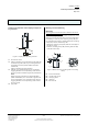
Figure 1: Display and operating elements
A1 IR-sensitive sensor
A2 LED for indicating normal operating mode (LED off)
or addressing mode (LED on); it is extinguished au-
tomatically once the physical address has been
transferred;
LED for indicating IR signal reception
A3 Magnet (not included in delivery) for contactless
toggling between normal operating mode and ad-
dressing mode for transferring the physical address
Note:
When using the programming magnet AP 590H
(5WG1 590-8AH01) or a commercial magnet it has
to be moved within 3 cm of the IR receiver lens for
toggling between normal operating mode and ad-
dressing mode.
A4 type plate
Montage und Verdrahtung
Mounting
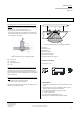
Mounting the IR receiver decoder S 450 to a wall or ceil-
ing with the mounting clamp (Figure 2)
Via the mounting clamp (B3) and the countersunk screw
(B2) the IR receiver decoder (B1) can be mounted either
horizontally or vertically. The mounting clamp (B3) can
be mounted either visibly or hidden where the mounting
clamp (B3) must be swivelled by 180°.
- Attach the mounting clamp (B3) with the screw (B2) to
the wall or ceiling.
- Slide the mounting clamp (B3) into the guide rail (B4)
of the IR receiver (B1).
B2
B4
B3
B2
B1
B3
B4
B5
B4
B4
Figure 2: Wall and ceiling mounting with a mounting
clamp
B1 IR receiver decoder
B2 counter-sunk screw
B3 clamping device
B4 guidance
B5 bus terminal