
Data Sheet for Product

GAMMA instabus
Technical product information
May 2019
IR receiver decoder S 450 5WG1 450-7AB03
Siemens Switzerland Ltd DS02 Update: http://www.siemens.com/gamma
Smart Infrastructure
Global Headquarters
Theilerstrasse 1a © Siemens Switzerland Ltd 2019
CH-6300 Zug Subject to change without further notice
4
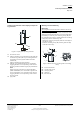
Mounting the IR receiver decoder S 450 to a mounting
support (Figure 3)
The mounting support (C3) must provide an opening for
the IR receiver (C1) of at least
35 mm.
- Snap the rose (C4) onto the IR receiver (C1).
- Then slip the retaining spring with its nibs (C2) along
the edges of the IR receiver's casing (C1) to the front
until a tight fit is achieved.
C1
C2
C3
C4
Figure 3: Mounting on a mounting support
C1 IR-receiver
C2 spring nibs
C3 mounting support
C4 rose
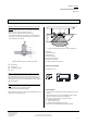
Notes on installing the IR receiver decoder to a ceiling
(Figure 4)
The IR receiver decoder can be mounted directly into a
fluorescent luminaire (D3) or at any other mounting lo-
cation where its lens has an unobstructed line of sight to
the IR transmitter.
Mounting variants for the IR receiver decoder (Figure 4,
D6):
- horizontally (using mounting clamp)
- vertically (using mounting clamp)
The IR receiver decoder is incorrectly mounted (D5) if it is
within the cone of lights (D4).
X
D7
D6
D5
D3
D4
D2
D1
Figure 4: Mounting options for ceiling installation
D1 ceiling
D2 raised ceiling
D3 luminaire
D4 cone of lights
D5 incorrect mounting
D6 correct mounting
D7 area of optimum reception
Dimension drawing
Dimensions in mm
29
26
25
67,5
75
General Notes
• The operating instructions must be handed over to the
client.
• Any faulty device is to be sent together with a return
delivery note of the local Siemens office.
• For any technical questions, please consult:
+49 (911) 895-7222
+49 (911) 895-7223
support.automation@siemens.com
www.siemens.com/automation/support-request