
Data Sheet for Product

instabus EIB
Technical Product Information
June 2003
Shutter switch N 524 5WG1 524-1AB01
(DC 24 V, 4 x 1 A)
Technical manual N 524, 4 pages Siemens AG
Automation and Drives Group
Update: http://www.siemens.de/gamma
Siemens AG 2003 Electrical Installation Technology
Subject to change without prior notice P.O.Box 10 09 53, D-93009 Regensburg
2.10.1.12/2
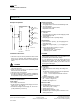
Example of operation
Shutter Switch
N 524
L1 N
AC 230 V
+ -
DC 24 V
M
=
Motor
Channel A
Motor
Channel B
Motor
Channel C
Motor
Channel D
DC drives
b
u
s
c
o
u
p
l
i
n
g
u
n
i
t
M
=
M
=
M
=
instabus EIB
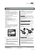
Installation instructions
• The device may be used for permanent interior instal-
lations in dry locations within distribution boards or
small casings with DIN rail TH35-7.5 according to EN
60715.
V
DANGER
• The device must be mounted and commissioned by an
authorised electrician.
• When connecting the device, it is important to ensure
that the device can be isolated.
• The device may not be opened.
• For planning and construction of electric installations,
the relevant guidelines, regulations and standards of
the respective country are to be considered.
Technical specifications
Power supply
• Bus voltage: via the bus line
• N 524 electronics: integrated power supply unit for AC
230V (+10% / -15%), 50 Hz
• External DC voltage for motor supply: 6V, 12V or 24V
(to be protected by a fuse 4A T)
Operating elements
• 1 learning push button:
for toggling between normal mode/addressing mode
• 4 x 2 push buttons:
for local operation of the DC drives,
independent of the EIB
Display elements
• 1 red LED:
for checking the bus voltage and for displaying normal
mode/addressing mode
• 1 green LED:
for displaying the 230 V operating voltage
Inputs/outputs
• mains connection: 2-pole (L, N), for supplying the in-
ternal electronics
• External DC voltage: 2-pole (+, -), for supplying the
drives
• 4 drive outputs (relay contacts): 4 x 2-pole
- Rated voltage: DC 24 V
- Rated current: max. 1 A per output
- Switching cycles: >20.000
CAUTION
- The total switched current, which is limited by the per-
mitted printed conductor load, may not exceed 4 A at
the terminals for the external DC voltage!
- It is not permitted to connect DC drives without limit
switches to the outputs (e.g. drives with built-in pulse
transmitter for position control) as the drive or the sun
guard might be damaged.
Connections
• Load circuit:
Screw terminals for mains voltage, DC voltage and
drives.
The following conductor cross sections are permitted:
- 2 x 0.5... 2.5 mm² single core or
- 2 x 0.5... 1.5 mm² finely-stranded with connector
sleeve,
insulation strip length 9 ... 10 mm.
• Bus line: screwless bus terminal
0.6 ... 0.8 mm ∅ single core,
insulation strip length 5 mm.
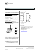
Mechanical data
• Housing: plastic
• N-system DIN-rail mounted device,
width: 6 MU (1 MU = 18 mm)
• weight: approx. 410 g
• fire load: approx. 5550 kJ ± 10 %
• installation: clip-on mounting onto a rail TH35-7.5 ac-
cording to EN 60715.