
Data Sheet for Product

instabus EIB
Technical Product Information
June 2003
Shutter switch N 524 5WG1 524-1AB01
(DC 24 V, 4 x 1 A)
Siemens AG N 524, 4 pages Technical manual
Automation and Drives Group
Electrical Installation Technology
Siemens AG 2003 Update: http://www.siemens.de/gamma
P.O.Box 10 09 53, D-93009 Regensburg Subject to change without prior notice
2.10.1.12/3
Electrical safety
• Degree of pollution (according to IEC 60664-1): 2
• Type of protection (according to EN 60529): IP 20
• Overvoltage category (according to IEC 60664-1): III
• Bus: safety extra-low voltage SELV DC 24 V
• Device complies with EN 50090-2-2, EN 60669-2-1
Electromagnetic compatibility
• complies with EN 61000-6-2, EN 61000-6-3 and
EN 50090-2-2
Environmental conditions
• Climatic withstand capability: EN 50090-2-2
• Ambient operating temperature: - 5 ... + 45 °C
• Storange temperature: - 25 ... + 70 °C
• Relative humidity (not-condensing): 5 % to 93 %
Approval
• EIB-certificate
CE mark
• In accordance with EMC guideline (residential and
functional buildings) and the low voltage guideline
Location and function of the display and
operating elements
A
1
A
2
A
3
A
4
A5
A
6
A
9
A8
A
7
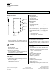
Diagramm 1: Location of operating and display elements
A1 Learning push button for toggling between normal
and addressing mode for transfer of the physical
address
A2 LED for displaying normal mode (LED off) or ad-
dressing mode (LED on); it is automatically extin-
guished once the physical address has been trans-
ferred
A3 Plug for bus connecting terminal
A4 LED for displaying the operating voltage
A5 Pushbuttons for local operation of the shutter drives
Channel A to D
A6 Type label
A7 Screw terminals for connecting the mains voltage
A8 Screw terminals for connecting the DC voltage
A9 Screw terminals for connecting the DC drives
Mounting and wiring
General description
The N-system DIN-rail mounted device (6 MU) can be
inserted to N-system distribution boards, either surface-
or flush mounted and wherever rails TH35-7.5 according
to EN 60715 are available.
The connection with the bus line is carried out via a bus
terminal block.
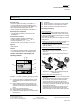
Installation of the DIN rail mounted device
(Diagramm 2)
- Hang the device (B1) into the DIN rail (B2) and
- rotate the device downwards until the slide bar audibly
clicks into position.
Dismantling the DIN rail mounted device
(Diagramm 2)
- Remove all connected cables,
- press the slide bar (C3) downwards with a screw-
driver and
- remove the device (C1) from the DIN rail (C2) with a
swivel action.
B1
C1
C2
C3
B2
Diagramm 2: Installing and dismantling the DIN-rail
mounted device
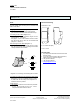
Removing the bus terminal
(Diagramm 3)
- The bus terminal is located on top of the shutter switch
N 524 (D1)
- The bus terminal block (D2) consists of two sections
(D2.1 and D2.2), each with four terminal contacts.
Care should be taken not to damage the two test
sockets (D2.3) by accidentally connecting them to the
bus conductor or with the screwdriver ( when trying to
remove the bus terminal ).
- Carefully insert the screwdriver in the wire entry slot
underneath the bus terminal (D2) and pull the bus
terminal forwards out of the shutter switch N 524 (D1).