
Data Sheet for Product

instabus EIB
Technical Product Information
June 2003
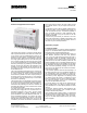
Shutter switch N 524 5WG1 524-1AB01
(DC 24 V, 4 x 1 A)
Technical manual N 524, 4 pages Siemens AG
Automation and Drives Group
Update: http://www.siemens.de/gamma
Siemens AG 2003 Electrical Installation Technology
Subject to change without prior notice P.O.Box 10 09 53, D-93009 Regensburg
2.10.1.12/4
Note:
Care should be taken as there is a risk to short circuit
the bus voltage when removing the bus terminal block
with a screw driver.
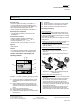
Plugging in the bus terminal
(Diagramm 3)
- Place the bus terminal (D2) to the guide slot and
- push the device backwards until it reaches the stop.
Connecting the bus cables
(Diagramm 3)
-
The bus terminal (D2) is suitable for single core con-
ductors with 0.6 ... 0.8 mm Ø.
- Strip approx. 5 mm of the insulation from the conduc-
tors (D2.4) and plug in them into the terminal block
(D2) (red = +, black = -).
Disconnecting the bus cables
(Diagramm 3)
- Remove the bus terminal block (D2) and the conduc-
tors (D2.4) of the bus cable by rotating them simulta-
neously backwards and forwards.
Diagramm 3: Connecting, disconnecting the bus cables
Connecting the mains and DC voltage and shutter drives
- The connections are carried out using screw terminals.
- Strip approx. 9-10 mm of insulation from the conduc-
tor, slide under the wire clamps of the respective ter-
minal and screw into position.
Cross sections:
• The following conductor cross sections are permitted:
- 2 x 0.5... 2.5 mm² single core or 2 x 0.5... 1.5 mm²
finely-stranded with conductor sleeve.
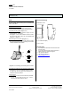
Dimension drawing
Dimensions in mm
b
90
44
55
45
b = 6 module units (MU)
1 MU = 18 mm
General Notes
• Any faulty device should be returned to the local
Siemens office.
• If you have further questions about the product,
please contact our Technical Support:
℡ +49 (0) 180 50 50-222
#
+49 (0) 180 50 50-223
! adsupport@siemens.com
D1
D2
D2
D2.4
D2
D2.4
5 mm
D2.1 D2.2
D2
D2.3