
Data Sheet for Product
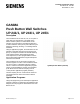
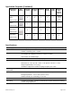
Table Of Contents

Technical Specification Sheet
Document No. 154-098
November 14, 2012
Siemens Industry, Inc.
Page 1 of 3
GAMMA
Push Button Wall Switches
UP 241/1, UP 243/1, UP 245/1
Description
The Push Button UP 24x has one, two, or four pairs of
upper and lower push buttons. The middle of the
device contains a panel, into which labels can be
inserted, as well as LEDs for orientation lighting and
for status indication. Each pair of push buttons may be
defined for switching, dimming, or controlling shutters
and blinds.
Using an application program, the Push Button UP 24x
transmits commands through the Bus Coupling Unit
(BCU), for example to actuators for defined switching
on/off, dimming lamps, raising/lowering shutters,
louver adjustment, or other programmable functions.
See the appropriate Application Program Description
manual for more details.
The Push Button UP 24x and a DELTA frame are
mounted together on a BCU. The Push Button UP24x
can only function in combination with Bus Coupling
Unit UP 110/03 that contains an application program.
That is, the final installation consists of the hardware
(Push Button UP 24x with Bus Coupling Unit UP
110/03) and the application program (software).
The Bus Coupling Unit UP 110/03 and the frame are
not supplied with the device and must be ordered
separately.
Application Programs
Using ETS (Engineering Tool Software) the application
program is selected, its parameters and addresses are
assigned, and the program is downloaded to the Push
Button UP 24x.
Quadruple Push Button (UP 245)