
Data Sheet for Product

GAMMA instabus
Technical Specification
November 2008
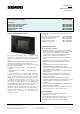
Colour touch panel UP 588/12 5WG1 588-2AB12
Colour touch panel UP 588/22 5WG1 588-2AB22
Accessories:
Design frame aluminium anodized 5WG1 588-8AB02
Design frame stainless steel 5WG1 588-8AB03
Design frame glass black 5WG1 588-8AB04
Design frame glass white 5WG1 588-8AB05
flush-type box 5WG1 588-8EB01
Technical Manual UP 588, 6 pages Siemens AG
Industry Sector, Building Technologies
Update: http://www.siemens.com/gamma © Siemens AG 2008 Business Sector - Electrical Installation Technology
Subject to change without further notice PO Box 10 09 53, D-93009 Regensburg
2.3.1.6/2
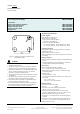
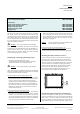
Figure 1: Drilling jig for cavity wall box Colour
touchpanel UP 588
V
DANGER
• The device may only be installed and commissioned by
an authorised electrician.
• The device may only be used in connection with the
named accessories, in particular the flush-type box.
• 230V devices which are not included with supply may
not be inserted in the flush-type box. It is also not
possible to loop through 230V cables.
• The prevailing safety and accident regulations should
be observed.
• The power supply voltage may only be connected to
the supply if the device has been fully installed.
• Protective isolation should be ensured between the
bus cable and the 230V power supply.
• For planning and construction of electric installations,
the relevant guidelines, regulations and standards of
the respective country are to be considered.
Technical specifications
Power supplies
• Bus voltage: via the bus line
• External power supply for:
• Colour Touch panel UP 588/12
230 V AC ±10%, 50/60 Hz
• Colour Touch panel UP 588/22
18 – 36 V DC, 400 mA, base isolated comp. 230 V
14 – 28 V AC, 400 mA, base isolated comp. 230 V
Operating elements
• Programming button to toggle between normal and
addressing modes
• Reset button to reset the device
• Resistive analogue touch with contact-sensitive area on
the display
Display elements
• Red programming LED for displaying normal/addressing
mode
• Graphics-capable TFT colour display 320 × 240 pixels
(1/4 VGA) with LED background lighting
Connections
• Bus line: KNX bus terminal, screwless
0.6... 0.8 mm ∅ solid, stripped length 5 mm.
• USB socket mini typ B (use only if needed for image
and symbols load)
• Power supply
stripped length: 6...7 mm
The following conductor/conductor cross-sections are
permitted:
- 0.5...2.5 mm
2
solid
- 0.5..0.1.5 mm
2
finely-stranded
Mechanical data
• Housing: Touch panel: plastic
• Frame: plastic
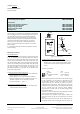
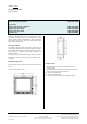
• Dimensions of visible surface at glass frame
(W × H × D): 244 × 176 × 4 mm
• Dimensions of visible surface at aluminium- and
stainless steel frame (W × H × D): 193 × 155 × 4 mm
• Mounting depth in flash-type box: 64 mm
• Installation: is screwed into the corresponding flush-
type box
• Dimensions of corresponding flush-type box (W × H ×
D): 161.5 × 135 × 64 mm, not included with supply
• Weight: approx. 510 g